Documentation
Class Slides
Diagram
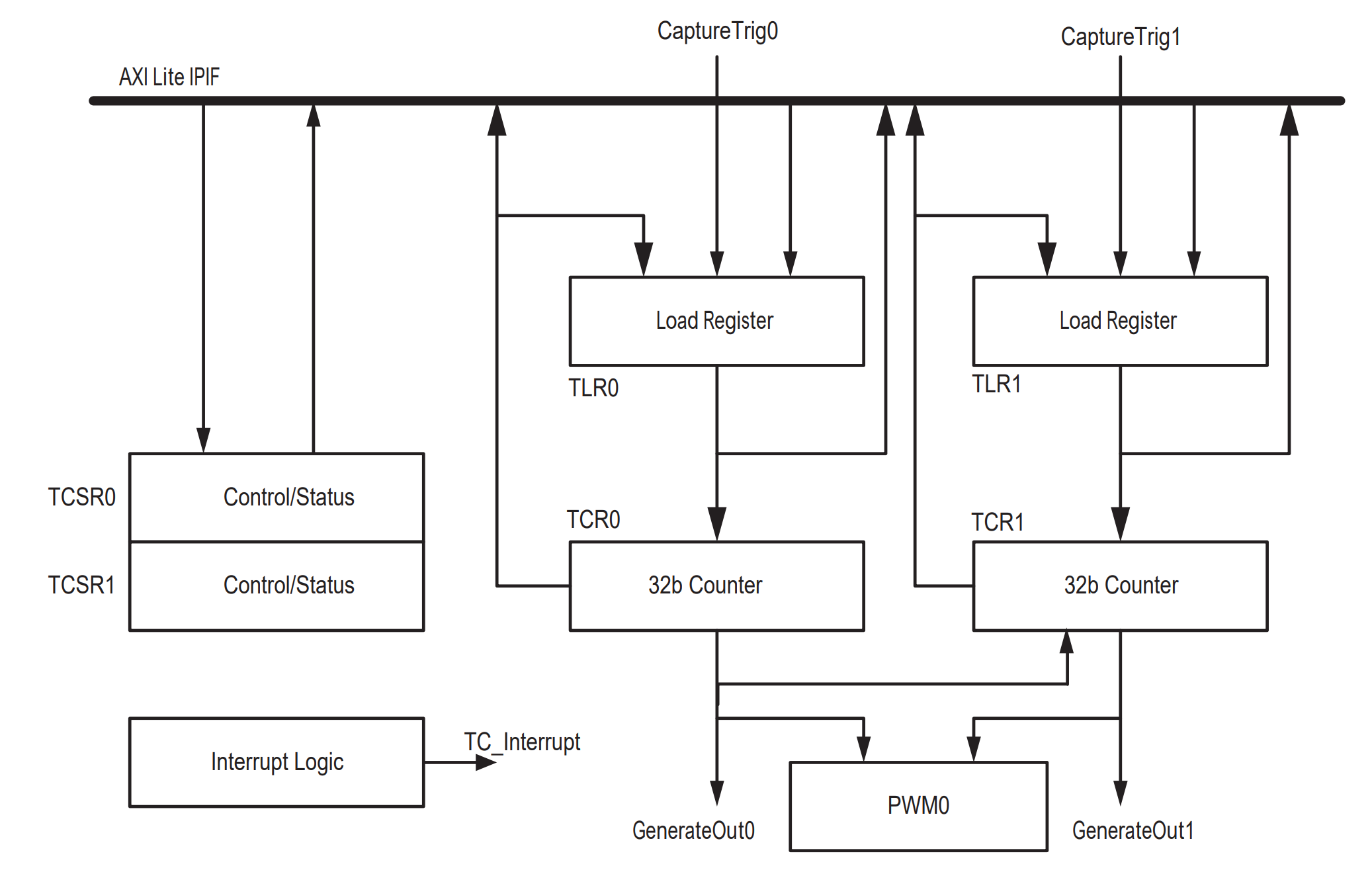
The hardware timers that you will access are Xilinx’s AXI Timer. Here’s a block diagram of the AXI timer taken from the data sheet.
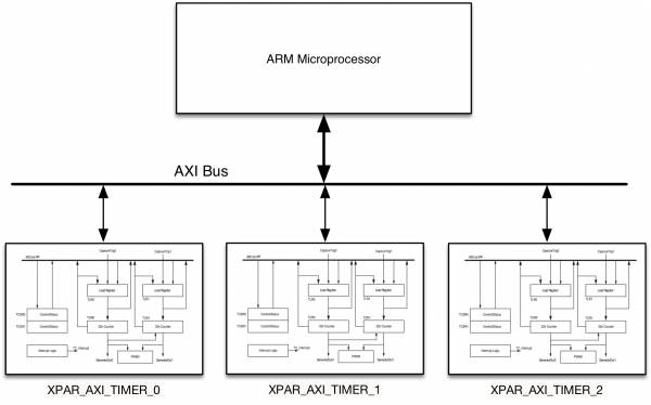
The hardware system we will use contains THREE of these timers, and they are named timer_0, timer_1, and timer_2, as shown below.
The xparameters.h file contains information you need about the timers (in particular the base addresses and the clock frequency).
NOTE: Do not copy the code below into your own code. Just include xparameters.h and use the defined values, e.g., XPAR_AXI_TIMER_2_BASEADDR.
/* Definitions for peripheral AXI_TIMER_0 */
#define XPAR_AXI_TIMER_0_DEVICE_ID 0
#define XPAR_AXI_TIMER_0_BASEADDR 0x42800000
#define XPAR_AXI_TIMER_0_HIGHADDR 0x4280FFFF
#define XPAR_AXI_TIMER_0_CLOCK_FREQ_HZ 100000000

/* Definitions for peripheral AXI_TIMER_1 */
#define XPAR_AXI_TIMER_1_DEVICE_ID 1
#define XPAR_AXI_TIMER_1_BASEADDR 0x42840000
#define XPAR_AXI_TIMER_1_HIGHADDR 0x4284FFFF
#define XPAR_AXI_TIMER_1_CLOCK_FREQ_HZ 100000000

/* Definitions for peripheral AXI_TIMER_2 */
#define XPAR_AXI_TIMER_2_DEVICE_ID 2
#define XPAR_AXI_TIMER_2_BASEADDR 0x42880000
#define XPAR_AXI_TIMER_2_HIGHADDR 0x4288FFFF
#define XPAR_AXI_TIMER_2_CLOCK_FREQ_HZ 100000000
Overview of Timer Hardware
The timer hardware is pretty complex and provides lots of functionality. However, we will only be using a subset of the features provided. As such, you need to carefully study at least the highlighted sections of the Xilinx documentation:
- Functional Description (we will only use generate mode in combination with cascade mode)
- Interrupts
- Register descriptions
As discussed in the manual, the timer consists of two 32-bit counters. Each counter has its own control/status register, that controls whether the counter is running, whether it is counting up or down, whether it auto-reloads, whether it generates an interrupt, etc. The counter values cannot be set directly, but instead are set indirectly through a load register (loading enabled through the control/status register).
The two counters can be cascaded to form a single 64-bit counter. This is referred to as cascade mode. In cascade mode, almost all of the control is done via a single control register (TCSR0) as the other control registers are mostly ignored in this mode.
You will be using the timers in both “count up” and “count down” modes. Counting up is most useful for timing duration between events (such as timing how long it takes to run a function), while count down is useful for generating periodic interrupts each time the counter expires and auto-reloads.
Register Descriptions
Here are some basic descriptions of each hardware register (see the documentation for full details):
- TCSR0/TCSR1: Control/Status Registers. Used to change counter modes, start/stop the counter, enable/acknowledge interrupts, trigger loading the counter values from the load registers, etc.
- TLR0 / TLR1: Load Registers, dictates the value loaded into counters. These values are used when you trigger a load, or when the timer rolls over and you have auto-reload enabled.
- TCR0/TCR1: Counter Registers. Read-only. You read these registers to find out the current value of counters.
Operations
- To initialize the counters, you should do the following:
- write a 0 to the TCSR0 register.
- write a 0 to the TCSR1 register.
- set the CASC bit to 1 and the UDT0 bit to 0 in the TCSR0 register (cascade mode and up counting).
- To store a 0 into Counter 0 (i.e., reset Counter 0), do the following:
- set TLR0 register to 0.
- set the LOAD0 bit of TCSR0 to 1.
- set the LOAD0 bit of TCSR0 to 0.
- To store a 0 into Counter 1 (i.e., reset Counter 1), do the following:
- set TLR1 register to 0.
- set the LOAD1 bit of TCSR1 to 1.
- set the LOAD1 bit of TCSR1 to 0.
- To start the cascaded counter:
- set the ENT0 bit of the TCSR0 register to 1. When you do this, you must not disturb the other bits in TCSR0.
- To stop the cascaded counter:
- set the ENT0 bit of the TCSR0 register to 0. When you do this, you must not disturb the other bits in TCSR0.
Additional Notes
- After loading the counters with 0s to reset them, you must re-initialize them (see Step 1 above). In particular, make sure that you clear the load bit for both counters.
- The process for reading the two 32-bit counters and reassembling them into a single 64-bit number is described on Page 5 of the documentation.
- Search the xparameters.h file to find out the frequency for the timers. Always use the provided #defines as they are provided by xparameters.h. Do not use the actual numerical constants.