Table of Contents
Overview
Managing device interrupts is a critical part of designing embedded systems. Interrupts allow you to respond to the needs of different hardware devices quickly and efficiently, without needing to perform constant device polling. In computer systems there are often many different devices generating interrupts. An Interrupt Controller, “is an integrated circuit that helps a microprocessor (or CPU) handle interrupt requests (IRQ) coming from multiple different sources (like external I/O devices) which may occur simultaneously.”
In this lab you will create a driver for an interrupt controller than receives interrupt requests from the three Interval Timers you used last lab, and forwards a single interrupt request on to the ARM processor.
After your driver is complete, you will write a simple test application to verify your driver is working correctly. This test application will initialize each timer to generate interrupts at different rates, and use each interrupt to blink an LED.

Objectives
- Learn about interrupts in embedded systems, and the role of interrupt controllers.
- Gain more experience interacting with hardware devices from software.
- Learn how to write more complex device drivers, including using function pointers to implement callback functions.
- Learn how to set up periodic interrupts and write interrupt handling code for simple applications.
Preliminary
-
Hardware. Read about the Interrupt Controller Hardware.
- Driver Interface. Read through the interface for your driver, provided in interrupts.h.
- Although not specified in the .h file, your driver should have an ISR helper function that will run user-provided callback functions that were registered through
interrupts_register().
- Although not specified in the .h file, your driver should have an ISR helper function that will run user-provided callback functions that were registered through
- Building the code:
- Driver:
- This driver will be written in drivers/interrupts.c, which you must create yourself. Uncomment the two lines in the drivers CMakeLists.txt file so that the interrupts library is built.
- Application Code:
- Your test application should be written in lab4_interrupts/interrupt_test.c. For this lab, you will need to write your own CMakeLists.txt file, which you can base off of previous labs.
- As usual, update the top-level CMakeLists.txt and add a
add_subdirectory(lab4_interrupts)statement.
- Driver:
Implementation
Requirements
-
Write a driver for the Interrupt Controller, implementing the functions defined in interrupts.h. Consult the comments in this file for details on the behavior of each function, as well as the in-class discussion.
-
Implement the interrupt_test_run() function, such that:
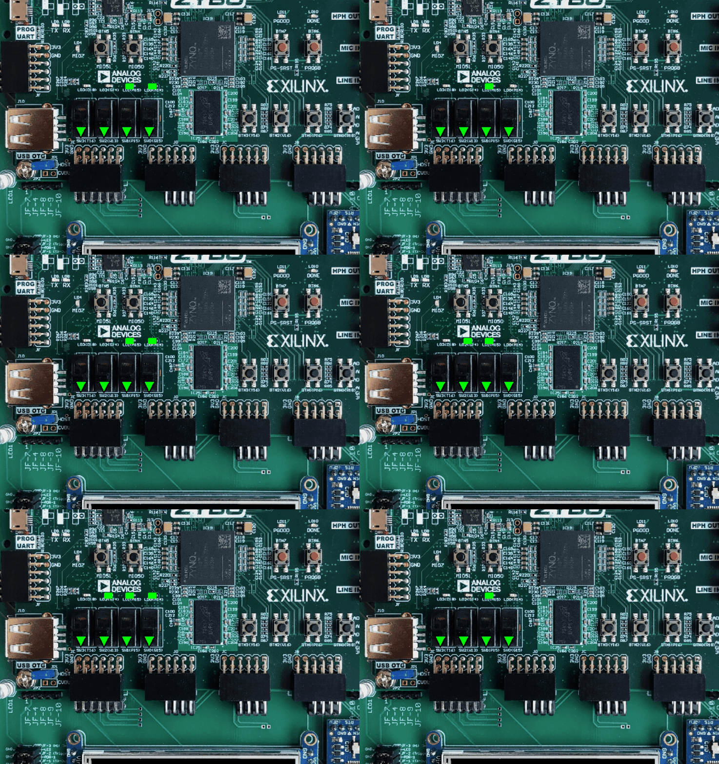
- Each of the three interval timers are running in count-down mode, and generating an interrupt at 10Hz, 1Hz and 0.1Hz.
- Create an interrupt handler function for each timer that toggles an LED.
- Your test code should match the behavior of the video above.
Files
- Submitted files: drivers/interrupts.c, lab4_interrupts/interrupt_test.c.
- Do not change or create any other files.
Other Notes
- Test Application Setup: Your test application will need to set up multiple devices:
- Remember to call
interrupts_init(),leds_init(), and each Interval Timer initialization function. - Enable device interrupt lines (IRQ output from Timer and IRQ input to Interrupt Controller)
- Register callback functions for each timer with the interrupt handler (see next item).
- Remember to call
- Interrupt handler functions: In your test application, you will have functions to handle the interrupt for each of your three timers. Within each of these callback functions, you should:
- (Optionally) Print a message so you know the function is being called.
- Acknowledge both:
- The interrupt output of the Interval Timer
- The interrupt input of the Interrupt Controller
(Think about which one you should do first – the order matters!)
- Flip the value of the appropriate LED.
- Like the previous two drivers, it would be good to write helper functions for accessing device registers. For example:
static uint32_t readRegister(uint32_t offset); static void writeRegister(uint32_t offset, uint32_t value); -
Take your time and be careful when creating
#definesfor register offsets and bit masks. Spending a few extra minutes to get these 100% correct will save you lots of debugging time. - Make sure you understand the behavior of the various Interrupt Controller registers. These registers have more complex behaviors than previous labs; however, you should find these behaviors quite helpful in completing your driver. Hint: Most of your driver functions can be implemented by making a single register read/write.
Submission
Follow the instructions on submitting source code to submit your code.
Grade Breakdown
- 80%: Driver and test application functionality.
- 20%: Coding standard