The PYNQ-Z2 board is equipped with an Analog Devices ADAU1761 24-bit audio codec chip. In the Hardware System, the audio_tx IP core, which is connected to the AXI processor bus, can store and play small chunks of audio data. By communicating with this hardware, you can play audio out over the 3.5mm jack, and capture audio input through an input line.
To play audio you will need to perform two major tasks, 1) Configure the codec chip using the external I2C bus, and 2) supply the audio_tx IP core with audio data.
Configuring the Codec Chip
The audio codec chip on the PYNQ-Z2 board must be configured before it will operate correctly. The codec chip is connected to the ZYNQ SoC via an I2C bus. The ARM-A9 processor on the ZYNQ has a built-in I2C controller, that drives this I2C bus. To configure the audio codec you will need to call the provided audio_config_init(). This function is provided as part of a user space audio_config driver.
Playing Audio Data
Audio Data Format
The audio hardware expects audio data in 24-bit PCM format, at 48kHZ. Accordingly, the audio_tx hardware contains small FIFOs to store several audio samples, which is sent to the audio chip at 48kHZ. You can read more about the PCM format in this document from the University of Toronto. Although this document is for a different hardware configuration than ours, the concepts still apply the same.
In order to play audio clips, you will want to open and read data from WAVE (.wav) audio files. Fortunately, WAVE files store their audio data in PCM format, so minimal processing will be required between reading the audio data from the WAVE file and writing in to the TX FIFOs.
Some information on the format of WAVE files:
Keep in mind not all WAV files are of the same format; for example, some WAVE files may be stereo or mono, the bit depth could be 16-bit, 24-bit, etc. Audacity is installed on the lab computers and can be used to convert between audio file formats.
Hardware System
While configuring the codec is done using I2C, sending the actual audio data (music, sound fx) to the codec is done using the I2S protocol. The audio_tx IP, at a rate of 48kHZ, removes audio samples from its FIFOs, and sends them to the codec chip via the I2S pins.
The internals of the audio_tx hardware are shown here:
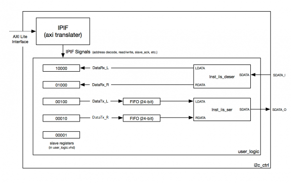
There are two FIFOs that are used to play audio on the left and right channel. You can add audio samples to these FIFOs by writing to the DataTx registers, although you will only want to do so when you know there is available space in the FIFO.
Interrupts
The FIFOs both have a depth of 1024, and if interrupts are enabled, the audio core will generate an interrupt if either FIFO is 75% or more empty (256 or fewer occupied entries in the FIFO).
Register map
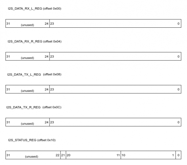
I2S_DATA_RX_L_REG: details
| Bits | Field Name | Default Value | Access Type | Description |
|---|---|---|---|---|
| 31-24 | Reserved | 0 | R | Always reads as 0 |
| 23-0 | DataRx_L | 0 | R | Left channel data from the input line |
I2S_DATA_RX_R_REG: details
| Bits | Field Name | Default Value | Access Type | Description |
|---|---|---|---|---|
| 31-24 | Reserved | 0 | R | Always reads as 0 |
| 23-0 | DataRx_R | 0 | R | Right channel data from the input line |
I2S_DATA_TX_L_REG: details
| Bits | Field Name | Default Value | Access Type | Description |
|---|---|---|---|---|
| 31-24 | Reserved | 0 | R | Always reads as 0? |
| 23-0 | DataTx_L | 0 | W | Data written to this register will be sent to the left channel of the audio out line. |
I2S_DATA_TX_R_REG: details
| Bits | Field Name | Default Value | Access Type | Description |
|---|---|---|---|---|
| 31-24 | Reserved | 0 | R | Always reads as 0? |
| 23-0 | DataTx_R | 0 | W | Data written to this register will be sent to the right channel of the audio out line. |
I2S_STATUS_REG: details
| Bits | Field Name | Default Value | Access Type | Description |
|---|---|---|---|---|
| 31-22 | Reserved | 0 | R | Always reads as 0 |
| 21 | DATA_RDY | 0 | R/W | Each time a new audio input sample is available in the DataRx registers, this bit will be set to 1. At any point the user can write a 0 to clear this bit. |
| 20-11 | TX_DATACOUNT_L | 0 | R | Indicates the number of values currently in the audio FIFO on the left channel. |
| 10-1 | TX_DATACOUNT_R | 0 | R | Indicates the number of values currently in the audio FIFO on the right channel. |
| 0 | INT_EN | 0 | R/W | Controls the interrupt generation coming from the audio hardware. Writes: Changes the interrupt generation operation. Reads: Returns the status of the interrupt generation (0 = interrupts disabled, 1 = interrupts enabled). |