Table of Contents
In this lab you will create a Programmable Interval Timer (PIT) in SystemVerilog that is accessible through the CPU’s memory-mapped AXI bus.
Objectives
- Gain experience with IP-based harware design.
- Learn about, and implement, the AXI protocol.
- Practice writing timing-sensitive HDL code.
Prelminary
In the real-time clock lab, you used a fixed-interval timer (FIT) from the IP catalog. As you may recall, the FIT generates interrupts at a fixed rate, based upon a single build parameter that cannot be changed once you have built the FPGA hardware. This makes the FIT very easy to use once your system is built, but the FIT is very inflexible. For this lab you are going to build a Programmable Interval Timer (PIT) in SystemVerilog and add it to the hardware system.
The PIT will be an AXI peripheral, allowing the CPU to control the PIT’s behavior through memory-mapped registers. The PIT logic itself is very simple, and you will likely have made more complex designs in a previous class. The challenging part of this lab is getting the AXI interface correct, which has strict protocol requirements.
You will work with two different Vivado projects in this lab:
- The first project will only contain your PIT module and some helper IP to generate AXI traffic. This project, which is the focus of Milestone 1, will only be used for simulation, as well as checking for synthesis errors.
- In Milestone 2, you will integrate your PIT into the ECEN 427 Vivado project, which contains the actual hardware system you have been working with in previous labs. This project will be used to generate a new bitstream that includes your PIT.
Specifications
PIT Hardware Design
Your PIT module must include the following:
- A 32-bit timer-counter that decrements at the system clock rate and that is controlled by elements described below.
- Interrupt: A single interrupt output (irq). The interrupt output is active high, and is asserted for a single cycle when the counter reaches 0.
-
Registers:
-
Offset 0x00: A 32-bit programmable control register, that must be readable and writeable from the CPU. You will control the behavior of the PIT by programming specific bits in the control register, as follows:
- bit 0 - enable: enables the counter to decrement if set to ‘1’, holds the counter at its current value if set to a ‘0’.
- bit 1 - interrupt enable: enables interrupts if set to a ‘1’, disables interrupts if set to a ‘0’.
- You may use the remaining bits in the programmable control register as you see fit.
- Ofset 0x04: A 32-bit delay-value register that must be readable and writeable from the CPU. This value controls the period of the interrupt output.
-
Offset 0x00: A 32-bit programmable control register, that must be readable and writeable from the CPU. You will control the behavior of the PIT by programming specific bits in the control register, as follows:
-
Reset: Your PIT must reset along with the rest of the system. Make sure to reset your PIT using the AXI resetn signal.
- It would be good to reset your PIT into a state equivalent to the FIT, so that you can test that it’s working without needing to perform any register writes. Thus:
- Reset the offset 0x00 control register to 3 (i.e., enable the counter and enable interrupts).
- Reset the offset 0x04 delay-value register to 1,666,667 (16.67ms at 100MHz, which is the same period as the FIT).
- It would be good to reset your PIT into a state equivalent to the FIT, so that you can test that it’s working without needing to perform any register writes. Thus:
PIT Behavior
- The timer-counter should auto-reload (i.e., when the timer-counter reaches 0, it should be reloaded based on the delay-value register, and continue decrementing).
- If you disable the counter, and then re-enable it, it should just continue as if it had not been disabled.
- Interrupts should not occur when disabled (i.e., if you happen to disable it exactly when the counter == 0).
- During normal operation, you program the delay-value register to contain a value that indicates how often an interrupt occurs. If you set the delay-value register to N, then an interrupt should occur every N cycles. For example, when the delay-value register contains a ‘2’, the interrupt output is a square wave with a 50% duty cycle. When the register is set to ‘3’, an interrupt occurs every third cycle. You don’t have to worry about what happens when the register is set to ‘0’ or ‘1’; that behavior is undefined.
- You will need to initialize your timer-counter at an appropriate time. This is best done when the delay-value register is changed.
Implementation
Milestone 1: Simulation Project
To grade your lab, the TAs will run the following:
  cd hw
  make sim_pit
  make clean
  make synth_pit
The make sim_pit target runs Vivado and does two things:
- It sources sim_proj.tcl, which builds your Vivado project (you don’t commit your Vivado project to your repo, only this Tcl file).
- To create this file, you will need to make your own Vivado simulation project that contains the AXI VIP and your module, connected appropriately. The Tcl script can then be exported using the Write Tcl menu option, as as described on the vivado page.
- When this script is run, it should create a Vivado project with a block diagram that uses the AXI VIP to test your module.
- It sources run_sim.tcl, which simply runs functional simulation in Vivado. This means that the Vivado project must be set up with a SystemVerilog test bench that runs the VIP-driven simulation.
- The test bench must:
- Demonstrate writing and reading back the control registers. When you read back the control register, print it out using
$display. - Demonstrate writing and reading back the delay-value register. When you read back the delay-value register, print it out using
$display. - Demonstrate your PIT running with a delay-value of 4, with the PIT enabled and generating interrupts. Make sure it runs long enough to generate several interrupts.
- Demonstrate that the enable and interrupt enable bits of the control register work properly.
- Demonstrate writing and reading back the control registers. When you read back the control register, print it out using
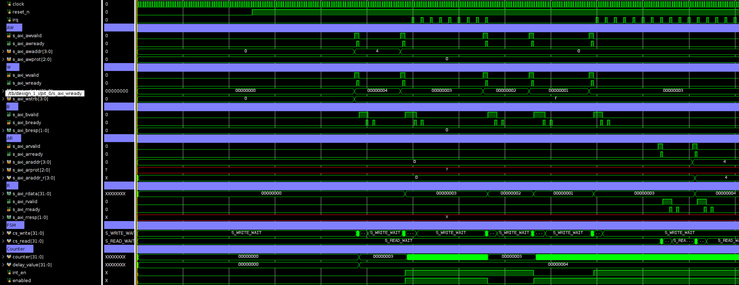
- You should have a pre-configured waveform file (.wcfg) set up that has appropriate signals added and organized in a way that the TAs can verify correct operation. Here is an example:
- The test bench must:
The make clean target removes all the temporary Vivado project files. You will need to update this command to delete your simulation project files, otherwise it will prevent you from recreating the project in the next step.
The make synth_pit target runs Vivado and does two things:
- Like the above target, it sources sim_proj.tcl to create your Vivado project.
- It performs Synthesis to ensure that your PIT design can be implemented in hardware. Synthesis will check certain design rules that simulation does not check.
You may want to go back and forth between these two targets as you work on your PIT design. If synthesis has errors, you will need to fix them and then go back to simulation again to verify that your changes didn’t break anything. Once both of these targets run without errors, you are ready to move on to Milestone 2.
IMPORTANT: Students frequently forget to commit all necessary files for the TAs to run the above commands. Make sure you commit your sim_proj.tcl file, your waveform configuration file, and any other necessary files to your repository. It is recommended that your perform a fresh clone of your repository and run the above commands to make sure that everything is committed that needs to be.
Milestone 2: Integration
Once you are confident that your PIT is working correctly, integrate it into the ECEN 427 Vivado project. See the Vivado documentation for information about creating a Vivado project with the existing ECEN 427 hardware system.
Here are some tips to help you integrate your PIT:
- Make sure you connect up all of the ports
- Make sure you assign your PIT an address
- You don’t need to remove the FIT from your system. Just don’t enable its interrupt.
- You will not need to add any external ports for your IP. The only extra port that you are adding is the interrupt line and it will be an internal connection. Remember that external ports are ports that connect to a pin on the FPGA.
- Make sure that the AXI connection is hooked up to the AXI interconnect. This will involve adding a new master connection to the interconnect.
- The interrupt line from the PIT should be connected to the userspace AXI Interrupt Controller.
After it is integrated:
- Verify that all of the connections are hooked up properly by running ‘Validate Design’
- Make sure you compile a new bitstream. See Compiling a New Bitstream.
Final verification:
- Pull down the new bitstream onto your PYNQ board, and replace your boot bitstream with the new one that includes your PIT.
- Update the
int_rateapplication to use your PIT instead of the FIT, and verify you are getting interrupts at the expected rate.
Make sure to commit:
- Your changes to the ECEN 427 project. You will need to export the Tcl file for the project, overwriting the provided ecen427.tcl file.
- Your new bitstream (both the .bit file and the .bin file).
How to Get Started
- Review the available documentation on using the Vivado software and simulating AXI IP.
- Write the PIT module, implemented in pit.sv
- Write your test bench to simulate your PIT module to make sure it works correctly.
- Complete the rest of the requirements described above.
Submission
Follow the submission instructions. Make sure that you have pushed up all your new hardware to Github, including at least:
- (Milestone 1) The sim_proj.tcl file that will be used to create your simulation project.
- (Milestone 1) The waveform configuration file.
- (Milestone 1) Your pit.sv changes.
- (Milestone 2) The changes to the ecen427.tcl file.
- (Milestone 2) Your new ecen427.bit bitstream.
- (Milestone 2) Your bitstream packaged into the ecen427.bit.bin format.