A few things to note about the hardware system that we have provided to you:
- The ps7_0 block corresponds to the ARM-A9 CPU, which is running the Linux software and all of the software you will write in this class. This is a hard CPU, meaning it is implemented directly in silicon. The rest of the IP blocks in the design correspond to RTL modules that will be implemented in the FPGA fabric.
- The processor connects to the axi_interconnect_0 block, which is the main system bus. This allows memory-mapped access from the CPU to the 11 peripherals in the system.
- AXI GPIO Documentation: There are several physical I/O pins on the FPGA chip that connect to the RGB LEDs, LEDs, switches and buttons on the PYNQ board. The GPIO modules provides an interface between the processor bus and these physical pins. Each group of pins are connected to their own AXI GPIO module.
- Fixed Interval Timer (FIT) Documentation: fit_timer_0 has been configured to generate an interrupt every 16.67ms.
- AXI Interrupt Controller Documentation As you can see, user_intc has three interrupt inputs, fit_timer_0, btns_gpio and switches_gpio. The interrupt controller generates an interrupt output, which is connected to an interrupt line of the CPU.
- AXI CDMA Documentation
- Audio:
- Video:
Interrupt System & UIO
Here is simplified system diagram that only contains interrupt-relevant stuff.
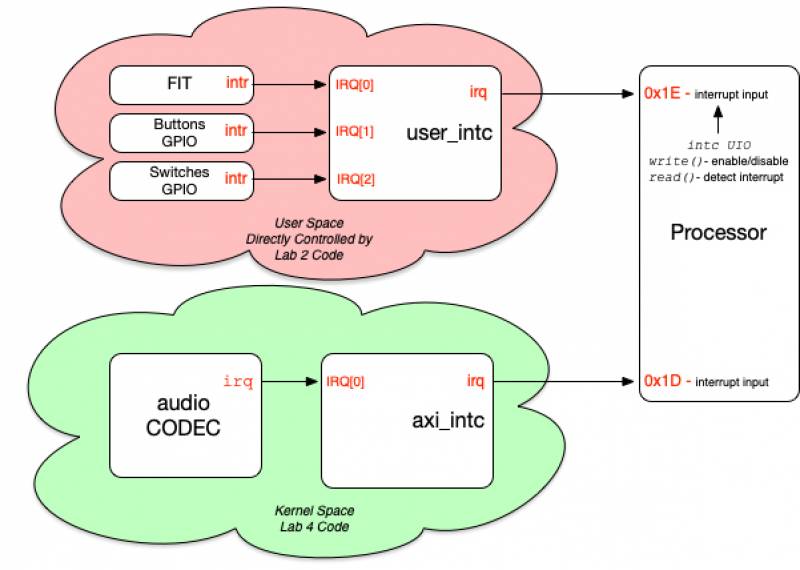
UIO
In the diagram above, the hardware in the pink bubble will be primarily controlled by userspace drivers (Lab 2). The UIO provides a way for userspace drivers to access the hardware.
Important: The interrupt lines running from the FIT and GPIO modules to the interrupt controller run between two devices that are controlled by userspace drivers. As such, the system is not configured to inform Linux that these interrupt lines even exist. Your userspace drivers will be responsible for detecting and handling these interrupts. Thus, for the buttons and switches GPIO, the UIO is only used to allow userspace to access the hardware registers.
For the user_intc, the setup is different. The interrupt line from the intc is connected to the CPU, which is controlled by the kernel. In this case we rely on the interrupt functionality of the UIO driver to detect in the kernel when an interrupt occurs. The UIO driver will then notify userspace that an interrupt has occurred. The userspace driver will then read the user_intc registers to determine which interrupt(s) occurred and then handle the interrupt(s) appropriately.