Table of Contents
This lab page is under construction and subject to change.
Overview
In this final lab, you will create another piece of custom digital hardware, which will be capable of modifying the graphics on the screen in an accelerated manner. Rather than relying on the processor to draw each pixel of the graphics, you will be able to issue a command to your hardware accelerator to do this for you.
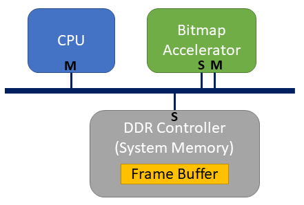
Your hardware accelerator will need the ability to change memory values in the pixel buffer. This means that it will act as a master on the system bus, with the ability to initiate read and write operations. This is also means that this hardware will be much more complex than your PIT device, which was a slave device, and could only wait and respond to requests initiated by a master device (the processor).
Fortunately, we are going to make use of a modern digital design technology, High-Level Synthesis (HLS), which will automatically create our Verilog digital circuit from a far simpler C-code description.
Describing Functionality in C Code
HLS tools allow you to design hardware using C/C++ code (with some limitations; for example, code that uses dynamic memory allocation or recursion isn’t supported). To use HLS, you must write your hardware behavior as a C/C++ function, and then run the HLS tools to convert this into a Verilog module. The function arguments will become top-level interfaces to your hardware block.
For this lab, you will implement the the fill_bitmap_region function, defined in bitmap_accelerator.h:
// Draw a rectangular region of pixels at (dest_x, dest_y), of size (width, height).
// Two modes are supported:
//    1. If fill_from_const is True, then the region is filled with a single
//        color, where RGB = (const_R, const_G, const_B)
//    2. If fill_from_const is False, then the pixels are copied from another
//        location in the frame buffer, at (src_x, src_y).  This allows you to
//        quickly draw the same sprite several times.
void fill_bitmap_region(uint8_t *frame_buffer, uint16_t src_x, uint16_t src_y,
                        uint16_t dest_x, uint16_t dest_y, uint16_t width,
                        uint16_t height, bool fill_from_const, uint8_t const_R,
                        uint8_t const_G, uint8_t const_B);
Create a bitmap_accelerator.c file where you implement this function. You can write this function now, or leave it empty and move onto the next step, but you need to make sure and create the file and function body before proceeding.
Some test code is provided to you in bitmap_accelerator_test.c to ensure that you implement it correctly. This will be used in the next step.
Note: You may want to review the HDMI Driver page to review the layout of the pixel buffer. Although you are interfacing directly with the pixel buffer in memory, the memory layout provided by the HDMI driver is nearly identical. The only exception is the byte ordering of colors; in hardware the color ordering is (green, blue, red) (when you used the HDMI driver you supplied it in (red, green, blue) and the driver re-ordered before writing to memory).
Vitis HLS
Creating a Project
Xilinx’s high-level synthesis software is called Vitis HLS. You can run this from the command-line using vitis_hls (after you have sourced the script to add the Xilinx tools to your PATH). If you run it this way, you will be presented with a new project wizard, where you will provide your files, select a part, etc. (similar to how you have created projects in Vivado).
Instead, we will create a new project using the provided proj.tcl script. Look through this script. It starts by creating a project named vitis_hls_proj. You will see that it adds your bitmap_accelerator.c file to the project (add_files), specifies which function will be synthesized to hardware (set_top), and adds the bitmap_accelerator_test.c file as a test bench code (add_files -tb). It also selects an FPGA part, and a target clock frequency.
To create your project run:
cd hw/hls/bitmap_accelerator
vitis_hls proj.tcl
Now open your project using:
vitis_hls -p vitis_hls_proj
In the Explorer pane (top-left) expand the Source and Test Bench groups, and make sure you can see your bitmap_accelerator.c and bitmap_accelerator_test.c files.
C Simulation
The next step will be to make sure your fill_bitmap_region function works correctly. If you haven’t already done so, write this function now. Then, in Vitis HLS, run C Simulation to verify that your function works correctly. This tool simply uses GCC to compile your test bench software, and runs the executable on your machine. No hardware is created yet.
The provided test bench, which you can inspect, runs your function four times, twice filling a region with a constant RGB value, and twice copying from one location in the frame buffer to another. For each operation the test bench has a golden frame buffer (ie a copy of exactly what the frame buffer should contain after the operation). If you implement the function incorrectly, it will print every byte that is mismatched with the golden copy.
C Synthesis
The next step is to synthesize your C code into a Verilog module. Run C Synthesis. This should take less than a minute, and then produce a report of the result. Look over the Performance & Resource Estimates section, and observe that the tool makes a prediction on how many FPGA resources will be used (LUT, FF, BRAM, DSP). The tool will also report a Latency value; however, this is worst-case prediction, as the latency of your code depends on what values you pass in for width and height. (You will probably see a very large latency value because width and height are 16-bit values which would mean you could theoretically ask the function to copy 2^16*2^16=~4 billion pixels. Of course we will never actually copy that many pixels.)
Note: If you want to automatically run C Synthesis when creating your project, add the line csynth_design to the end of your proj.tcl file.
Interfaces
Open and inspect the Verilog module that Vitis HLS produces. It is located in solution1/impl/verilog/fill_bitmap_region.v.
You don’t need to understand all the Verilog that is produced, but look over the module inputs and outputs. You should see:
- clock (ap_clk) and reset (ap_rst) inputs
- Control inputs/outputs that allow us to start the module and know when it’s done processing (ap_start, ap_done, ap_idle, ap_ready).
- Data inputs for all of our function arguments.
These simple inputs and outputs are useful if we want to connect this module to other hardware modules (like you have done in ECEn 220); however, this isn’t what we want for our hardware system. Rather, we want to be able to control this module from software. This requires an AXI bus interface, with control and data signals accessed through hardware registers on the bus.
Fortunately, Vitis HLS can automatically create Verilog with various interfaces, including both AXI4-Lite slave and AXI4 master interfaces. Interfaces are one of many types of design directives that Vitis supports to guide how the Verilog is created. To add interface directives, open your bitmap_accelerator.c file, and then open the Directive pane (top-right). You should see different elements of your C code (functions, arguments, loops, etc) that you can apply directives to.
We need to create three main interfaces:
- An AXI4-Lite slave interface to control (ie. start) the module.
- An AXI4-Lite slave interface to provide function arguments. (This will actually be the same bus interface as #1).
- An AXI4 master interface, that allows access to the frame buffer in system memory.
Control Interface
To add this interface:
- Select the top-level function (fill_bitmap_region) in the Directives pane, right-click and choose Insert Directive.
- Choose the INTERFACE directive type.
- Change mode to s_axilite (slave, AXI4-Lite), and click OK to finish adding the directive.
Note: Directives can also automatically be applied through Tcl. You could add the following line to your proj.tcl (before csynth_design):
set_directive_interface -mode s_axilite fill_bitmap_region
Data Input Arguments
For each input (excluding frame_buffer), select the input from the Directives pane and repeat the above steps to add it to the AXI4-Lite interface. Or through Tcl (for the src_x port):
set_directive_interface -mode s_axilite fill_bitmap_region src_x
Frame Buffer AXI Master
The frame_buffer input is unique. Think about how your software code uses this argument. It is an input in the sense that the caller of your function provides a pointer address to the frame buffer. However, it is also used in your software through dereferencing to go out and read/write values in memory. This requires a more complicated interface.
To add this interface:
- Again, select the frame_buffer input in the Directives pane, and add an INTERFACE directive.
- For the mode, select m_axi (master, AXI4). This will create a master interface which will allow the hardware to initiate read/write operations on the bus.
- However, the hardware still needs to know the address of the frame buffer in memory. This will be provided like the other inputs, as an AXI4-Lite slave register. To indicate this, choose slave for the offset option (you may need to make the pop-up Directive Editor window larger to see this option).
- Click OK to finish adding this directive.
Or though Tcl:
set_directive_interface -mode m_axi -offset slave fill_bitmap_region frame_buffer
Now, re-run C Synthesis. Take a look again at the produced Verilog file. If you added the interfaces correctly, the only top-level ports you should see are the clock, the reset, the AXI4-Lite slave bus (comprised of several signals), the AXI4 master bus (comprised of several signals), and an interrupt output (we won’t be using this).
Updating your Hardware in Vivado
IP Export
As you did in Lab 5, the next step is to package your Verilog into an IP module that you can include in your Vivado project. Fortunately, you don’t have to do this manually; Vitis HLS will automatically package your IP. You can select Export RTL from the run menu, and output your IP to the hw/ip_repo folder. Or add this to the end of your proj.tcl:
export_design -format ip_catalog -output ../../ip_repo/fill_bitmap_region.zip
After running this you should unzip the files:
cd hw/ip_repo
unzip fill_bitmap_region.zip -d fill_bitmap_region
Then commit these IP files to your repo.
Connecting your IP in your Vivado Project
Add your new IP to your Vivado project like you did in Lab 5. Wiring up this IP will be slightly different, and more complicated, than your PIT. Follow these steps:
- Connect the clock input. This should come from the 100MHz clock output of the ZYNQ7 Processing System (FCLK_CLK0).
- Connect the reset input. This should come from the peripheral_aresetn output of the rst_ps7_0_fclk0 block.
- Attach the AXI4-Lite slave interface to the appropriate bus (same as Lab 5). In our system, the axi_interconnect_0 block implements the bus for memory-mapped 100MHz devices. Double click to reconfigure this bus and add another master port.
- Connect the new master interface (MXX_AXI) to the slave port on your IP (S00_AXI).
- Connect the clock and reset inputs on the bus to the same clock and reset used above.
- Open the Address Editor and assign an address to your block (/fill_bitmap_region_0/s_axi_control)
- Next, we need to connect the AXI4 master interface to the system memory. The DDR memory controller is actually internally part of the ZYNQ7 Processing System, so you won’t see it on the diagram, but you can enable slave connections to the processing system to allow master devices access to the system memory. You will see that one such input, S_AXI_HP0 already exists, which is connected to the axi_mem_intercon_1 bus and used by the Video system. This bus won’t work for us, since the Video system is running at a different clock rate (142 MHz, FCLK_CLK1). Instead, you will need to do the following:
- Double click to reconfigure the ZYNQ7 Processing System, go to PS-PL Configuration , expand HP Slave AXI Interface, and enable the S AXI HP1 interface.
- Add a new AXI Interconnect IP to your design, with one master and one slave port.
- Connect the master port of your HLS IP (m_axi_gmem) to the S00_AXI input.
- Connect the M00_AXI output to the newly added S_AXI_HP1 port on the processing system.
- Connect all clock inputs on the bus to FCLK_CLK0.
- Connect the ARESETN bus reset to the interconnect_aresetn output of the rst_ps7_0_fclk0 block.
- Connect the S00_ARESETN and M00_ARESETN resets to the peripheral_aresetn output of the rst_ps7_0_fclk0 block.
- Open the Address Editor and assign an address to the /ps7_0/S_AXI_HP1 entry. This should automatically be set to address 0, as shown below:

If done correctly, it should look something like this:
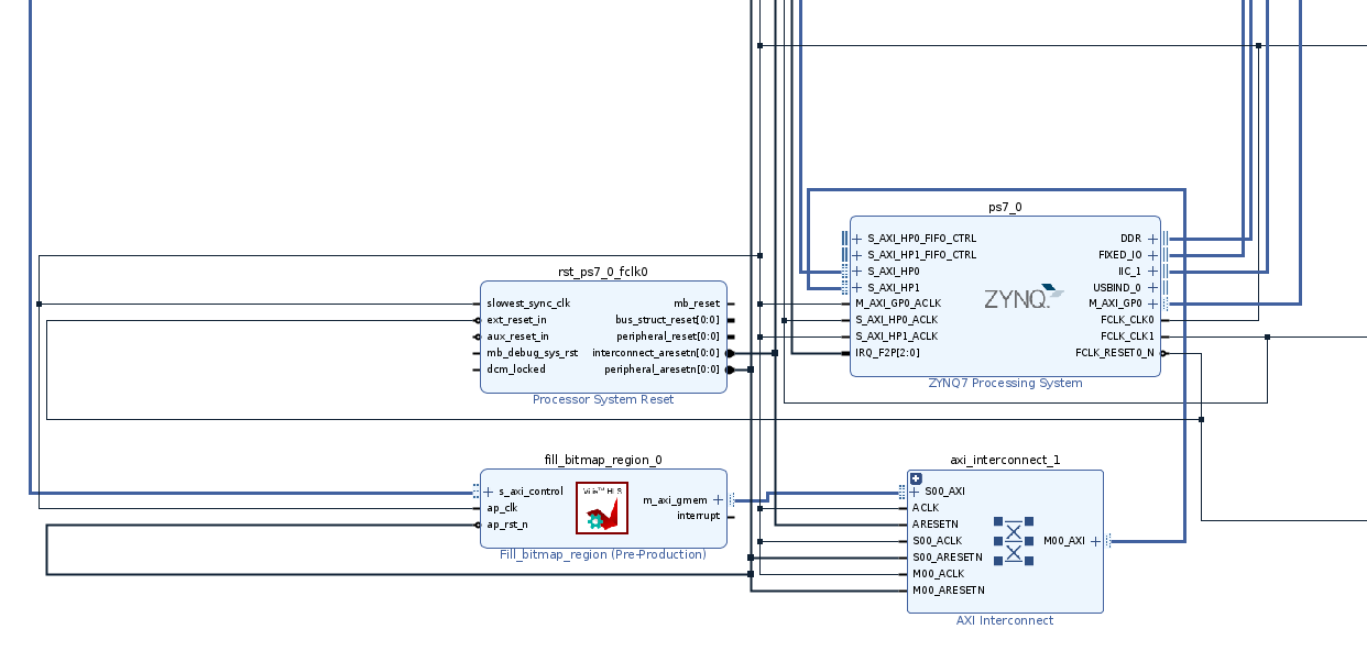
Click the Validate Design button (looks like a check mark) to ensure that your design is valid.
Compiling and Committing the Hardware
As with lab5:
- Save your hardware project changes by generating a new ecen427.tcl file (and commit to Git).
- Generate a new bitstream, copy it to hw/ecen427.bit and commit it to git.
- Add a new entry to the device tree, with a compatible field set to generic-uio, and a reg field that is the AXI slave address of your new IP.
- Go to the device_tree folder, run
make buildto generate new ecen427.bit.bin and ecen427.dtbo files, and commit them to git. - Pull these changes down on your PYNQ board, and run
make installin the device_tree folder to update the hardware bitstream and device tree on your board.
You are now ready to write software that uses your hardware accelerator.
Running Your Accelerator from Software
Testing Your Accelerator
Take a look at the ip_repo/copy_bitmap_region/drivers/fill_bitmap_region_v1_0/src/xfill_bitmap_region_hw.h file. This header file, which is automatically created by Vitis HLS, provides the full register map of the AXI slave interface. For example, you should see that bit 0 of register 0x00 (Control signals) is used to start your accelerator.
With this information you could write your own user space driver that accesses these registers via UIO (like you did in Lab 2). However, there is no need to do so, since Vitis HLS automatically creates such a driver for you. This driver is located in the various xfill_bitmap_region* files.
Copy these files to the fill_bitmap_region driver folder. This folder serves as a simple wrapper around the Xilinx-created driver. You should create a fill_bitmap_region.c file, and implement the three functions listed in the fill_bitmap_region.h file.
These functions are quite simple, and just need to call the appropriate functions that are listed in xfill_bitmap_region.h:
- To initialize the driver you will need to call XCopy_bitmap_region_Initialize. The first argument is a pointer to a XFill_bitmap_region struct that will be initialized by this function. The second argument to this function is InstanceName, which is the name you chose for your accelerator in the Linux Device Tree. Unlike the drivers you created in Lab 2 which used hard-coded /dev/ filenames, the Xilinx driver uses the device tree name to lookup the appropriate */dev/ file to use.
-
To call subsequent functions that read/write the device registers, such as:
void XFill_bitmap_region_Set_frame_buffer(XFill_bitmap_region *InstancePtr, u64 Data);you will provide a pointer to the XFill_bitmap_region struct you initialized earlier, as well as the data to set.
Once you implement these functions correctly, we have provided a frame_buffer_test application to test that it’s working. This application draws a red, green and blue square in the top-left of the screen, then copies these three squares to the middle fo the screen. It looks like this:
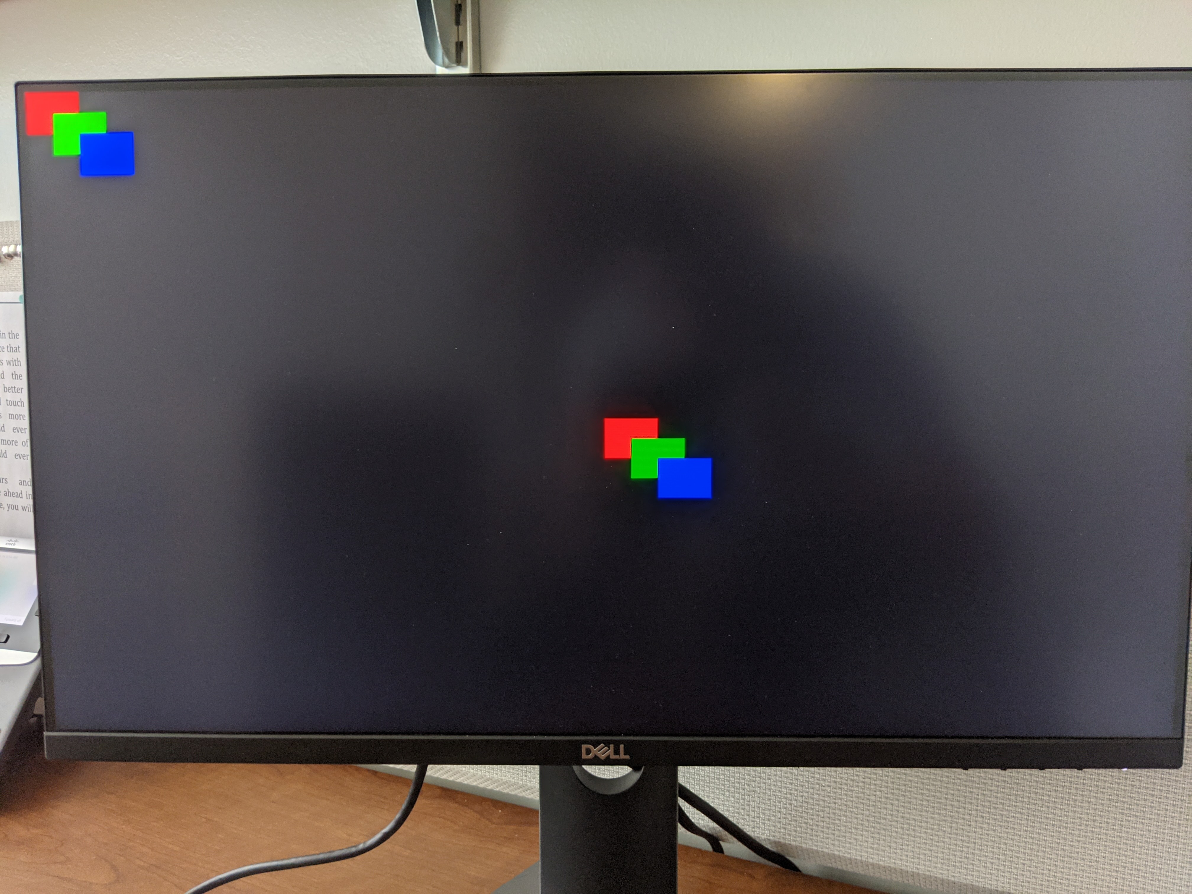
This application is worth looking through as an example on how to use your accelerator. One important thing to note: to use your accelerator, you need a pointer to the frame buffer. As shown in this application, you can retrieve this by making an IOCTL call to the HDMI driver.
Space Invaders Integration
Now that you have a working driver, you should make use of it in your Space Invaders game. While you are free to use it extensively, for pass-off, you only need to do two things:
- When the game starts, use your accelerator to clear the screen. Add a printf message that states how long it took to fill the screen.
- When you draw the five rows of aliens, use your accelerator to draw them quickly. Again, add a single printf message that states how long it took to draw them.
Your accelerator can be used to copy one alien to many different locations quickly. However, you may be wondering the best way to do this; since aliens can be destroyed, and can move around, you can’t always rely on one being at a specific location to copy from. To make this easier, we have added 40 extra rows of pixels below the screen that you can use to temporarily store your sprites. If you draw aliens to this “off-screen” region using the original software method, you can then reliably copy from these locations using your accelerator throughout gameplay.
Note: You are free to work with your lab3 partner(s) to perform this stage of the lab. However, make sure you commit the changes to your individual Github repository.
Submission
Use the usual submission instructions. The TAs will look over your files, and run your space invaders game and look for the two printf messages. Make sure all your hardware files (.bit.bin and .dtbo) and software files are committed, otherwise the TAs won’t be able to run your code properly.