Table of Contents
The following procedure gives detailed steps for how to program a Nexys 4 DDR board with a microblaze soft processor and run code on that same processor. It assumes that the board file for the Nexys 4 DDR board is already downloaded and added to vivado.
Create a New Vivado Project
- Run Vivado (
vivado) from terminal - Create Project
- Click Next
- Choose a project name and location and click next
- Choose RTL Project and check “Do not specify sources at this time” and click next
- At the top of the window select Boards
- From the list of boards highlight the Nexys4 DDR and click next
- If the board is not shown in the list, you need to download and add the board file to vivado.
- Follow the steps towards the bottom of this tutorial for instructions on how to obtain and add the board file
- Click Finish
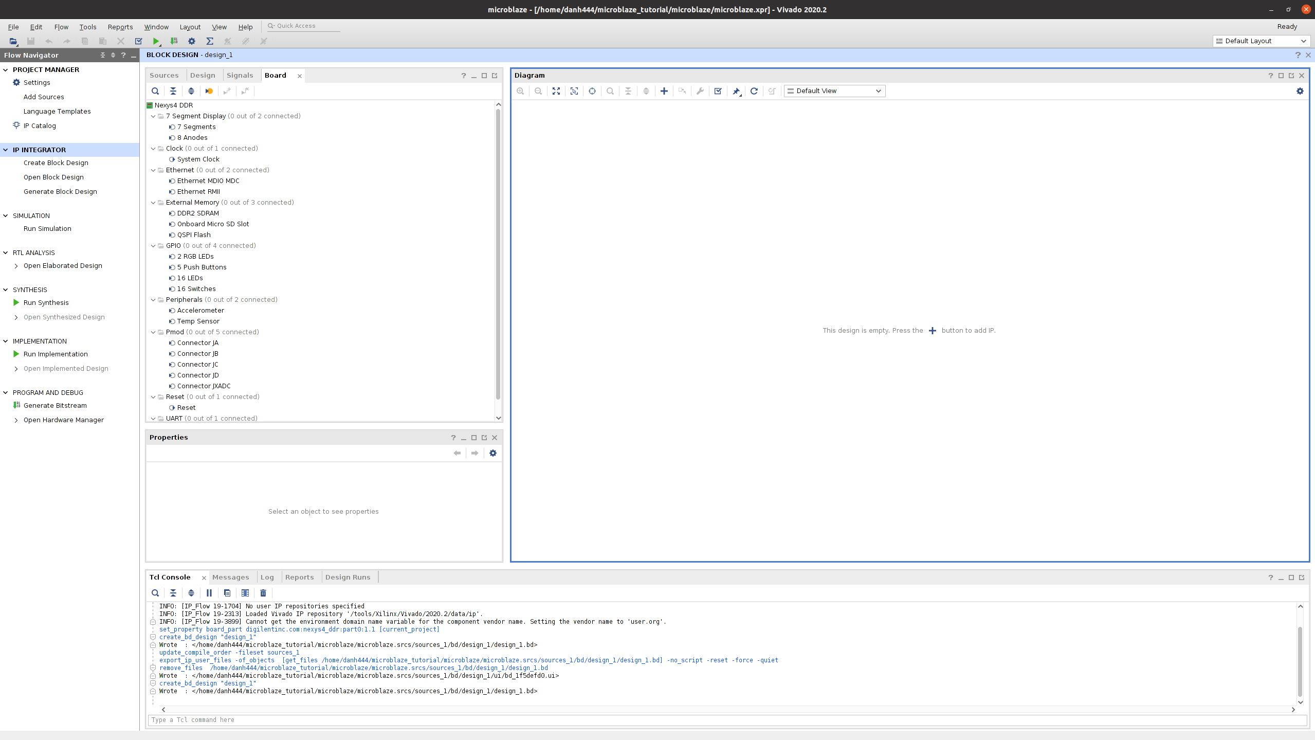
Create Block Design
- On the left in the Flow Navigator, under IP INTEGRATOR, select “Create Block Design”
- Choose a design name and click OK
- Select the board tab
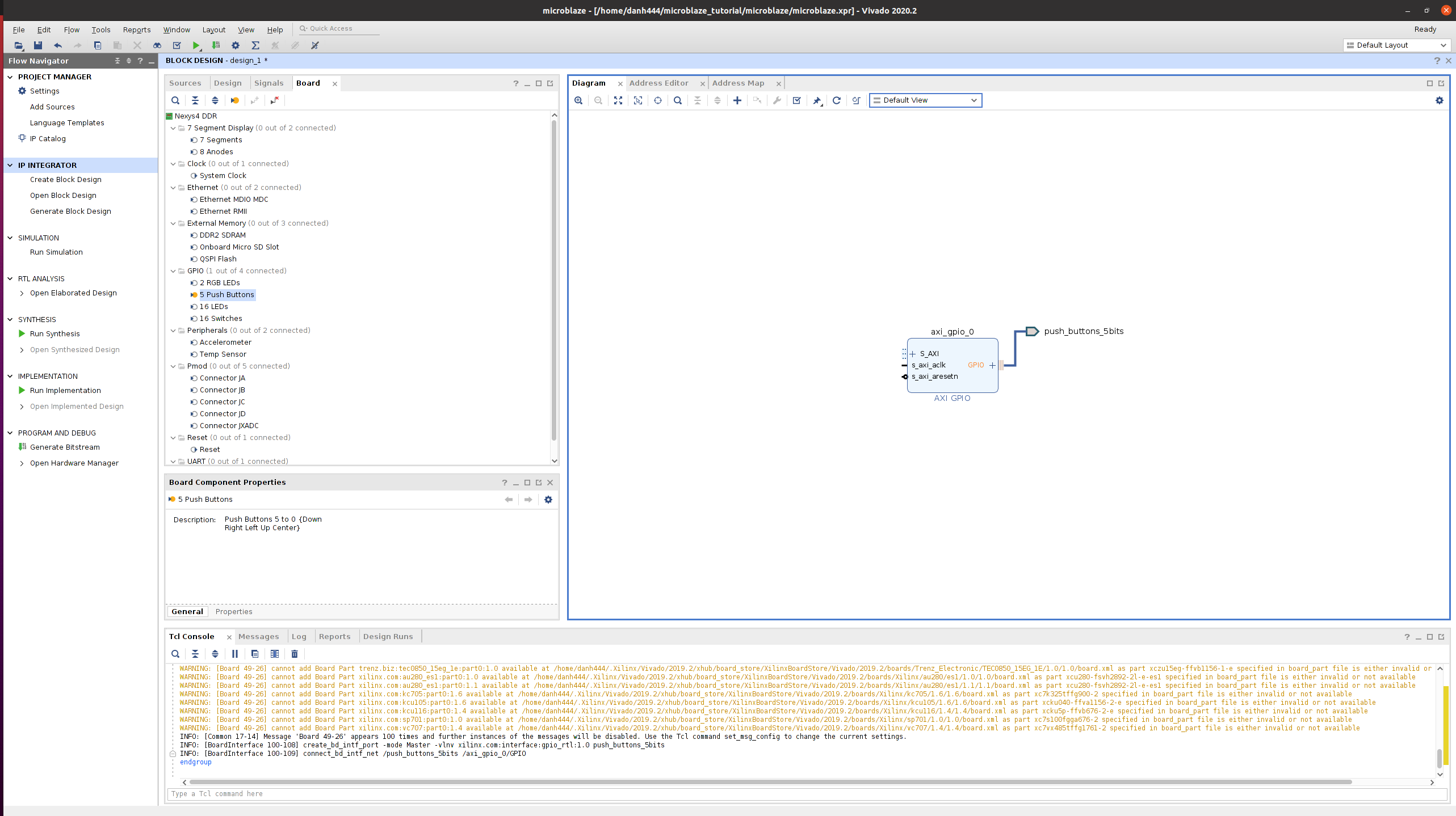
- Right click on the Push Buttons entry
- Select Connect Board Component
- In the popup, select Create new IP -> AXI GPIO -> GPIO and click OK
- In the board tab, right click on the LEDs
- Select Connect Board Component
- In the popup, select existing IP -> axi_gpio_0 -> GPIO2 and click OK
- In the board tab, right click on System Clock
- Select Connect Board Component
- Check the box next to “clock_CLK_IN1” and click OK
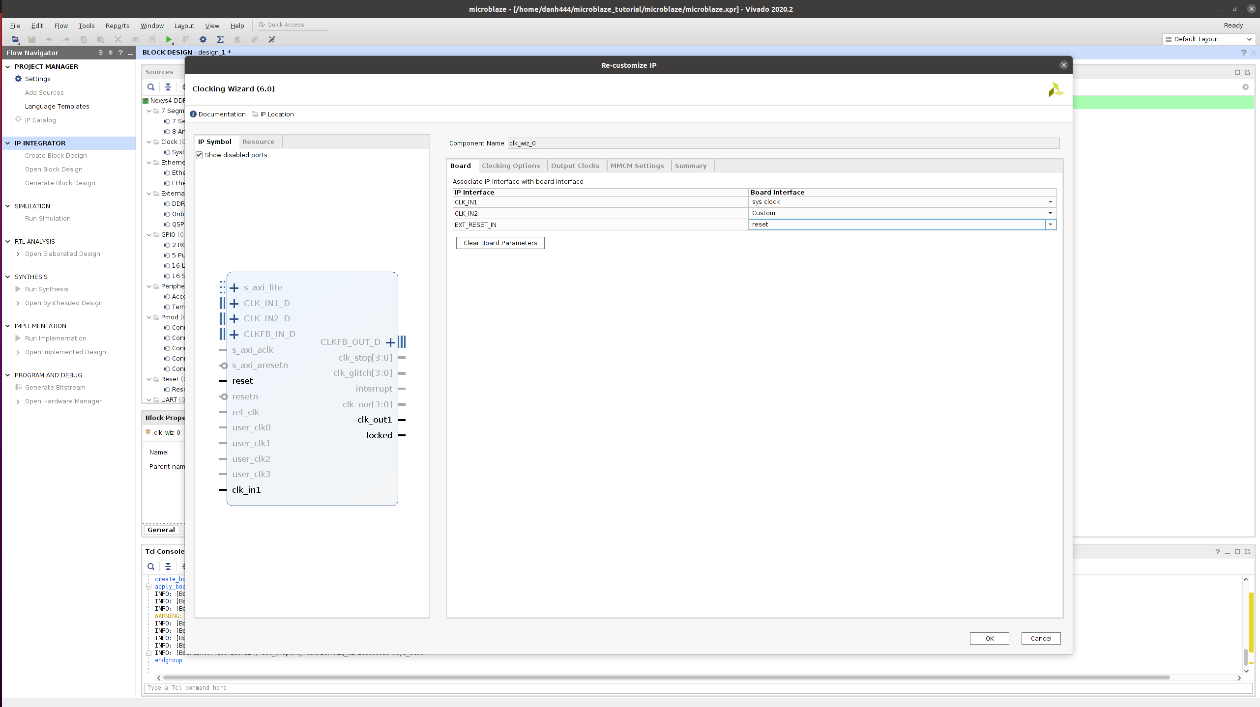
- Double click on the clk_wiz_0 block in the block diagram
- On the Board Tab, make sure that CLK_IN1 has sys clock selected
- For EXT_RESET_IN select reset
- Select Output Clocks tab
- Make sure that the clk_out1 box is checked and that the Requested Frequency is 100 MHz
- Select Active Low for the Reset Type
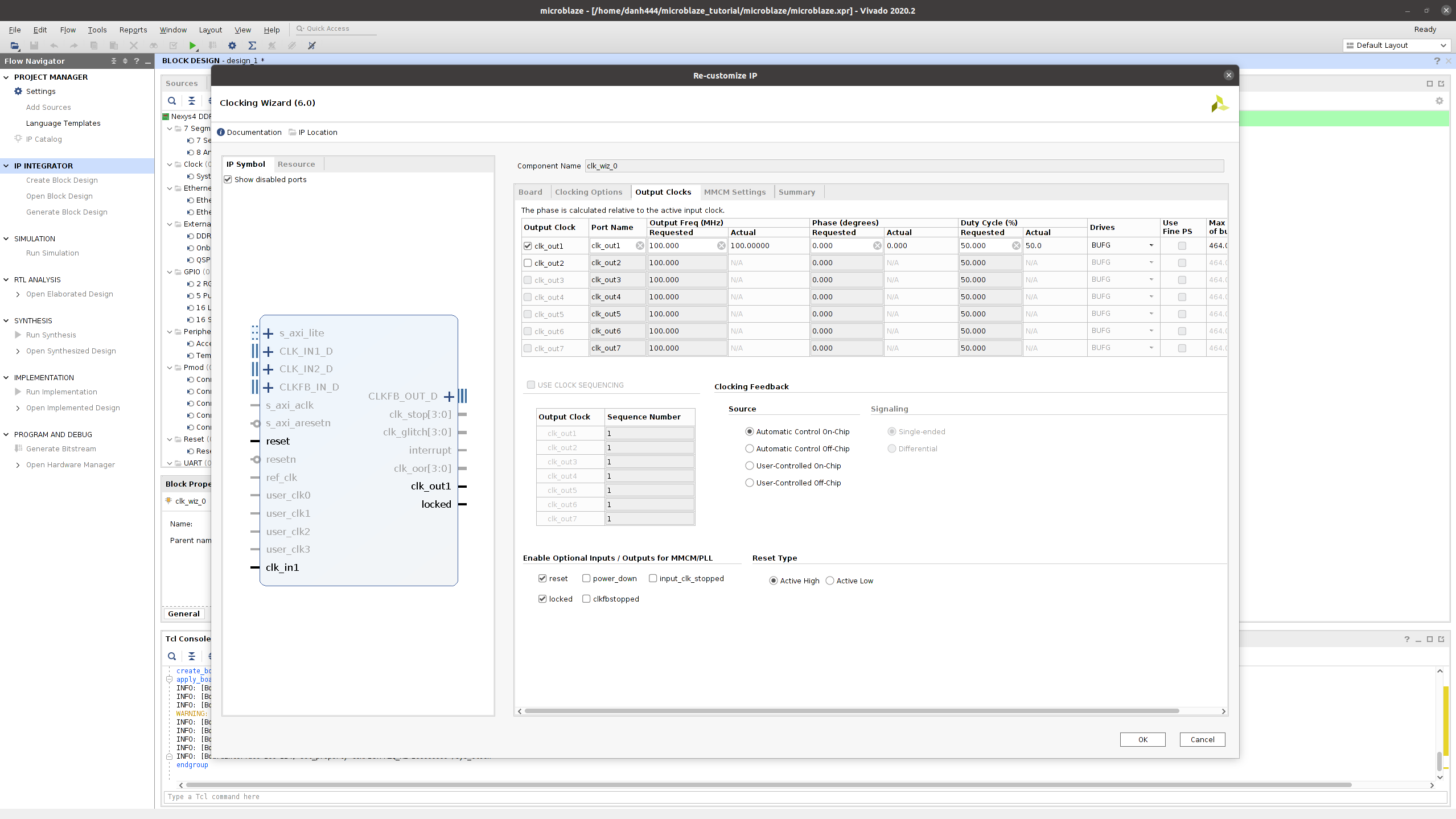
- Click OK
- Click “Run Connection Automation”
- Make sure the resetn box is checked
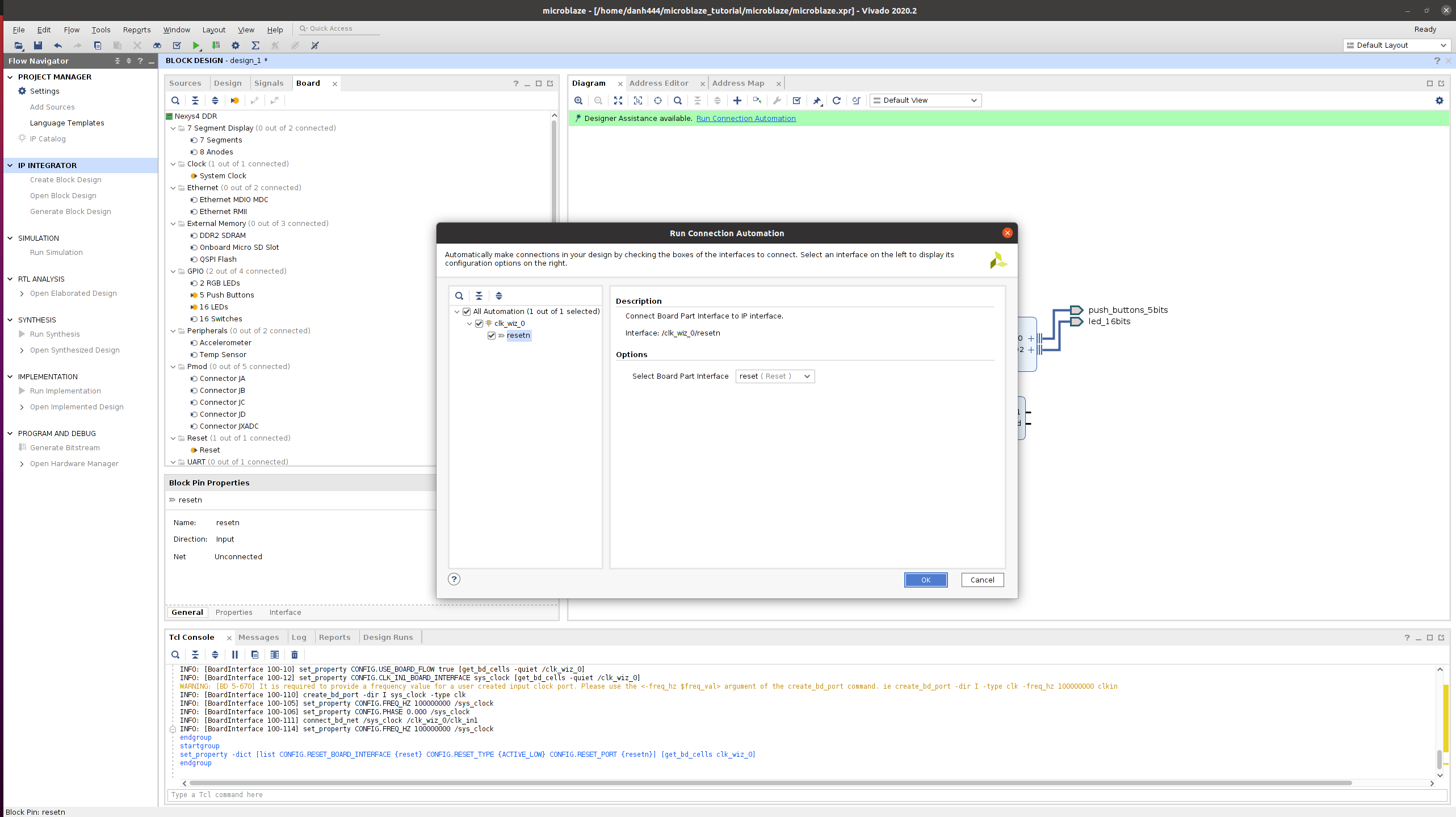
- Click OK
- In the Board tab, right click on USB UART
- Select Connect Board Component
- Select AXI Uartlite -> UART
- Click OK
- You can double click the new UART Block to check the UART settings
- Click the “Add IP” (Plus sign at the top of the block diagram)
- Search Microblaze
- Double click microblaze
- Click Run Block Automation
- Set Local Memory to 32 KB
- Click OK
- Click Run Connection Automation
- Check the box next to All Automation
- Click OK
Generate Bitstream
- Click the Validate design button
- Click OK
- On the sources tab, right click your block design and select Create HDL Wrapper
- Check Let Vivado manage wrapper and auto-update
- Click OK
- Under the Flow Navigator select “Generate Bitstream”
- Click Yes
- Click OK
- Wait
- On the next pop up click Cancel
- In the File drop-down select Export, then Export Hardware,
- Click Next
- Check Include bitstream and click Next
- Choose a name for your XSA filename and click Next
- I named mine dh_microblaze and saved it to /home/danh444/microblaze_tutorial/microblaze
- Click Finish
Program Board
- Click Open Hardware Manager -> Open Target -> Auto Connect
- Click Program Device -> xc7a100t_0
- Click Program
Launch Vitis
- Run Vitis (
vitis) in terminal window - Choose a Workspace and click Launch
Create the Platform Project
- Click File -> New -> Platform Project
- Choose a name for the platform project
- Click Next
- Under Hardware Specification, Browse to the XSA file you created
- Click Finish
Create the Application Project
- Click File -> New -> Application Project
- Click Next
- Select the platform you created
- Choose an application project name
- Click Next
- Choose Empty Application C++
- Click Finish
- Under your new application project, right click on src and click add file.
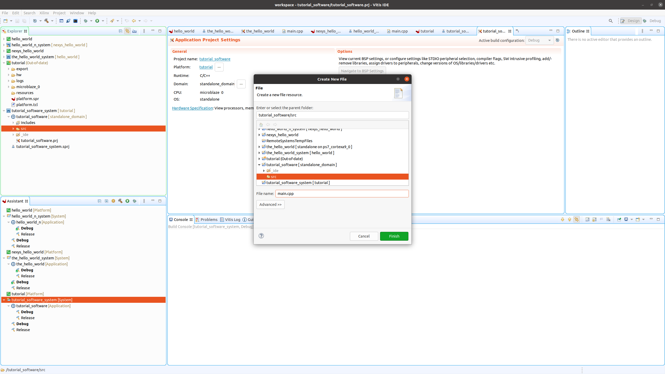
- Name it main.cpp and click Finish
- Add the following simple program
#include <stdio.h> int main() { printf("Hello World\n"); } - Save the file
- Right-click on your application project and select build project
Connect to UART
- In order to see the program output you need to connect to the board UART
- Open a separate terminal
- Enter the following command
- python3 -m serial.tools.miniterm /dev/ttyUSB1 9600
Application
- Right-click on your application project and select run as -> Launch on Hardware (Single application debug)
- You should see the message Hello World in the UART terminal
Sources
- This was done following this tutorial
- https://digilent.com/reference/vivado/getting-started-with-ipi/2018.2