Table of Contents
GitHub Classroom
Use the GitHub Classroom link posted in the Learning Suite for the lab to accept the assignment.
Objectives
- Become familiar with the tools used for this lab
- Understand how to setup a single board computer
- Be able to gain access remotely to the Raspberry Pi Zero 2 W
Overview
In this class we will be using the Raspberry Pi Zero 2 W (or Pi Z2W for short) as the platform to explore the fundamentals of computing taught throughout the semester. In this lab you will be setting up the single board computer so that it is capable of handling all the labs in this course. There are 3 parts to this lab:
- Flash and configure the Pi Z2W
- Gain remote access to the Pi Z2W
- Development environment setup
- Put all of the components together for future labs
Setting up the SD Card
In order to make use of the Pi Z2W, we will need to put an operating system onto its SD card. An operating system (OS), simply put, is a collection of programs which allows a user to interact with a device’s hardware. For users of PCs, this collection of programs is called Microsoft Windows, for Mac users macOS, and for Linux users there exists a wide variety of distros to choose from.
In this lab we will become familiar with a distinct version of Linux called Raspberry Pi OS (formerly known as Raspbian) which was made specifically for devices like the Pi Z2W.
- In order to load Raspberry Pi OS to the SD card we will use the Raspberry Pi Imager tool. On your lab machine go to the Activities menu (in the upper lefthand corner) and then type in
imager. Click on the icon that looks like a raspberry. You should see the following window open: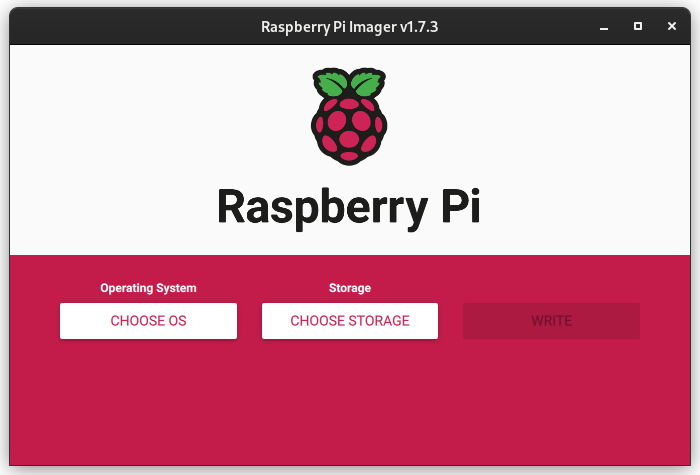
-
Select the CHOOSE OS option. Then click on Raspberry Pi OS (other) > Raspberry Pi OS Lite (64-bit). This is the OS that will be written to the SD card. Note that the Lite option means that there will be no point-and-click navigation with the OS like you would be used to in Windows and macOS. Instead we will use the command line to get around.
-
Next we will configure some of the OS settings by clicking on the
 icon. This brings you to the Advanced Options menu:
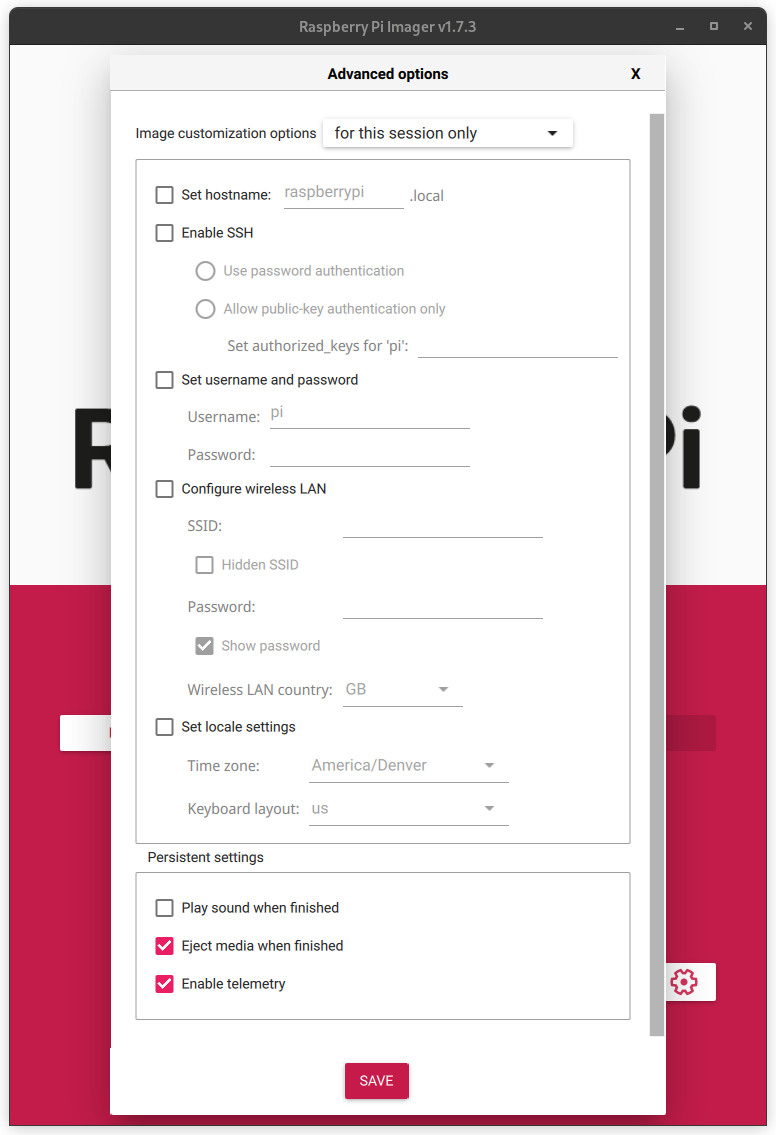
-
Change the following values in the menu according to the table below:
Setting Value Description Set hostname: doorbell-<your_netid>This will be the name of your Pi Z2W. This will make it easier to find on the network. Replace <your_netid>with your actual BYU NetID.Enable SSH: Check Enable SSH and select Use password authentication This allows you to login into your Pi Z2W from anywhere on the network with the sshtool by using a username and password.Set username and password: Any username and password you desire (make sure it is secure). We change these values from the default so that you can protect your projects. You are responsible for remembering this username and password! Any loss of these credentials may require you to re-setup your Pi Z2W. Configure Wireless LAN* SSID: name of WiFi network at home
Password:password of networkIn case you want to work with the Pi Z2W outside of the Digital Lab. Set locale settings: Timezone: America/Denver
Keyboard Layout: usThis makes sure that the region the Pi Z2W is in the MDT timezone with the US keyboard layout. *optional configurations
-
Now that we have correctly configured the OS settings, we will write the OS to the SD card that came with your Pi Z2W kit. Make sure that your SD card is plugged into the USB adapter and that the adapter is plugged into the lab computer.
-
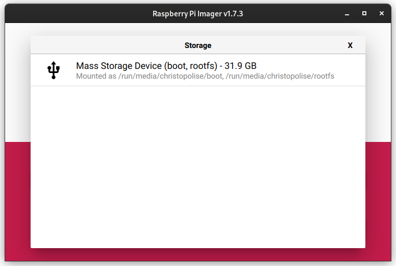
Select CHOOSE STORAGE on the imager. A window that allows you to select the SD card will pop up:
-
Select the SD card and click WRITE to start writing the OS to the SD card. A pop-up window will ask you if you want to erase all contents on the SD card before continuing, select YES and continue with the write process. The writing process will take a while.
-
Once the writing process finishes, remove the SD card from your laptop and insert it into the SD card slot of the Pi Z2W.
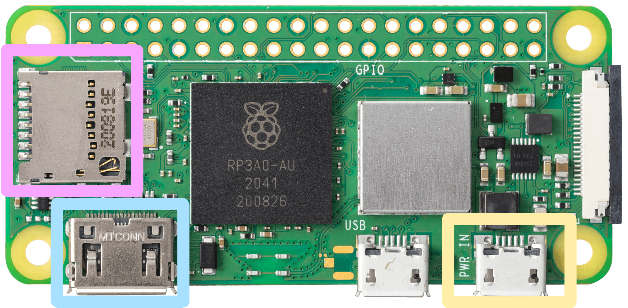
- Plug in the Power over Ethernet (PoE) adapter (the white brick) into the first micro USB port (the only one not circled in the figure at the beginning of this lab) to power up and supply internet to Pi Z2W. Power over Ethernet is a technology that provides both Internet and power at the same time. Only some Ethernet ports have it, but all of the ports in the Digital Lab do. It is not necessary to have power and the PoE adapter plugged in at the same time.
The boot process will take a while, so wait at least two minutes (or until the green light starts flashing) to move to the next section.
Connect to Pi Z2W
Now that your Pi Z2W has Raspberry Pi OS Lite installed and is connected to the lab network, we are able to connect to the it remotely using ssh. A remote connection means that you are able to log into a computer (like the Pi Z2W) from a different computer (like the lab machines).
-
Make sure you are able to find your Pi Z2W by opening up the terminal on your lab machine. This can be done either through finding it in the Activities menu or simply pressing
Ctrl+Alt+T. Once the terminal has opened, search for it by entering the command:ping doorbell-<your_netid>.localIf you receive a message like the following:
ping: doorbell-kitras.local: Name or service not knownthen the Pi Z2W is not connected to the lab network. Check the ethernet cable and make sure that everything is plugged in correctly then try again.
If you receive messages like:
 PING doorbell-kitras.local (192.168.86.48) 56(84) bytes of data.
 64 bytes from doorbell-kitras.local (192.168.86.48): icmp_seq=1 ttl=64 time=95.7 ms
 64 bytes from doorbell-kitras.local (192.168.86.48): icmp_seq=2 ttl=64 time=5.47 ms
 64 bytes from doorbell-kitras.local (192.168.86.48): icmp_seq=3 ttl=64 time=25.0 ms
 64 bytes from doorbell-kitras.local (192.168.86.48): icmp_seq=4 ttl=64 time=21.6 ms
 64 bytes from doorbell-kitras.local (192.168.86.48): icmp_seq=5 ttl=64 time=6.53 ms
Press
Ctrl+Cto stop the command. This means your lab machine can see the Pi Z2W and you are able to login withssh. -
Login to the Pi Z2W via
sshby typing in:ssh <your_username>@doorbell-<your_netid>.localYou will be asked to enter the password you chose earlier. When you type your password in Linux you won’t see anything show up in the Terminal window, but it is still being entered. Just type your password and press
Enterwhen you are done. -
A prompt will appear asking if you want to add the Pi Z2W to a list of trusted remote computers. Type in
yesto add the Pi Z2W to the trusted list. -
After entering in your login credentials, you should receive a prompt like the following to show that you are inside of the Pi Z2W:
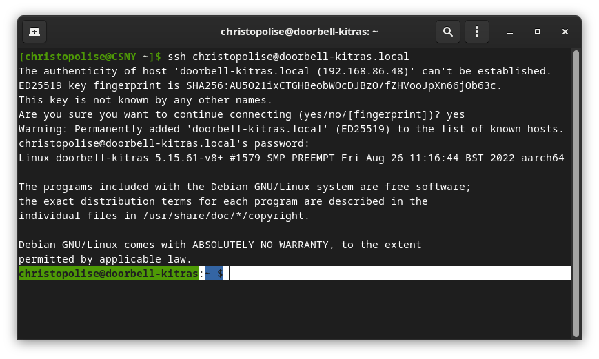
You can tell you are inside the Pi Z2W by looking at the string before the cursor. It should be
username@computer_nameor specifically<your_username>@doorbell-<your_netid>on the Pi Z2W. -
Now that you are logged into your Pi Z2W, we will download a script that will install all the dependencies we will need for future labs.
First, run this command:
wget https://byu-cpe.github.io/ecen224/assets/scripts/install.sh(For a long command like this, it’s easiest to copy and paste it into the terminal. Use
Ctrl+Shift+Vto paste into the terminal.)This will download the script to your Pi.
Next, run:
chmod +x install.shThis command will change permissions on the script, allowing you to execute (run) the .sh file. Lastly, run the script with:
./install.shYou will see print statements in the terminal logging the installation process. For the last step, it will ask for your password to apply all of the changes. This is the password you set on your Pi Z2W. Once you have entered your password and the script has finished, reboot your Pi with this command:
sudo reboot
Connect with Visual Studio Code
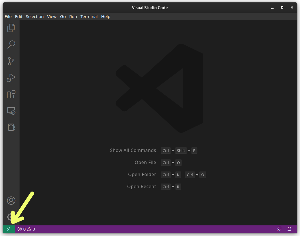
Next, we will connect to your Pi Z2W using VSCode using the Remote - SSH extension.
-
Open VSCode through the Activities menu on your lab machine. Look at the bottom status bar of the window. There should be an icon at the bottom left side of the screen:
-
If this icon is not there, that means the Remote - SSH extension is not installed. To install it, click on the extensions
 icon on the leftmost toolbar. This will open up the Extensions Manager where you can search for any type of tool you wish to add to your VSCode editor.
 -
Type in
Remote - SSHinto the search bar and click the Install button on the entry that says Microsoft underneath. -
Once the extension has successfully installed, you can now click on the green icon in the bottom left corner as seen in the figure above.
-
Click on this icon then select Connect to Host > Add New SSH Host. In this input box we will put the
sshcommand we used before to connect to the Pi Z2W through the terminal:ssh <your_username>@doorbell-<your_netid>.local.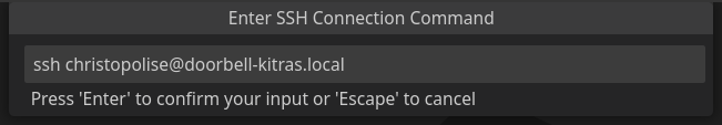
-
Then save this entry to your local
sshconfiguration file on our lab machine (either /home/… or /fsi/…):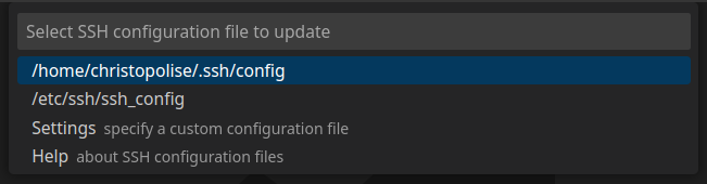
-
Click on the Remote SSH icon in the bottom left corner again and this time select the new
sshentry you just made by clicking Connect to Host > doorbell-<your_netid>.local. -
A new window will pop up and prompt you to enter in your Pi Z2W password. Enter in your password. If this is the first time you have connected to this device, it might take a few minutes to install all the necessary dependencies. After it connects, you can browse through files and code on your Pi Z2W from VSCode on your lab machine.
-
In the left toolbar on the window, click on files
 icon.
icon. -
Click on the Open Folder button and then click OK on the pop-up. This should put you into your home folder on Raspberry Pi OS.
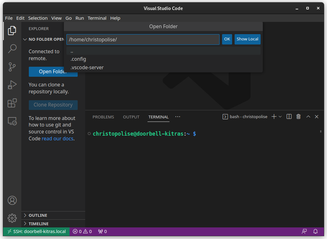
Now you can use the left pane of VS Code to view and edit files inside the home directory on the Pi Z2W.
Create SSH key for GitHub
All of the labs require you to write code and upload it to a version control service called GitHub. A GitHub account is required for this class. If you do not have an account you can create one here otherwise you are allowed to use your personal account for this class.
In order to allow our Pi Z2W to speak with GitHub, we will need to create an SSH key that will allow GitHub to know that the changes to the code online came from a trusted source (i.e. your Pi Z2W) and not from some impostor’s device (i.e. your arch-nemesis’s Pi Z2W).
-
To generate an SSH key, use the VSCode terminal (by clicking Terminal > New Terminal) - this creates a new instance of a terminal that is connected to your Pi Z2W. Type in the following:
ssh-keygen -t ed25519 -C "your_email_address"The tool will ask you several questions. For our purposes, the default values will suffice (i.e. just hit
Enteruntil it finishes) unless you desire to protect your key with a password (not recommended for this class; it would require you to enter in a password any time you want to use the SSH key). -
Once this is done you can find the contents of your new SSH keys by typing in
cat ~/.ssh/id_ed25519.pubNOTE: Make sure that you
catthe values ofid_ed25519.puband NOTid_ed25519. The contents in the.pubare meant to be shared with thepublic and the contents of the other file are not meant to be shared with anyone else. -
Copy the output of this file by selecting it and pressing
Ctrl-Shift-C. Then navigate in a web browser to your GitHub keys console (you must be signed into GitHub for this step to work). -
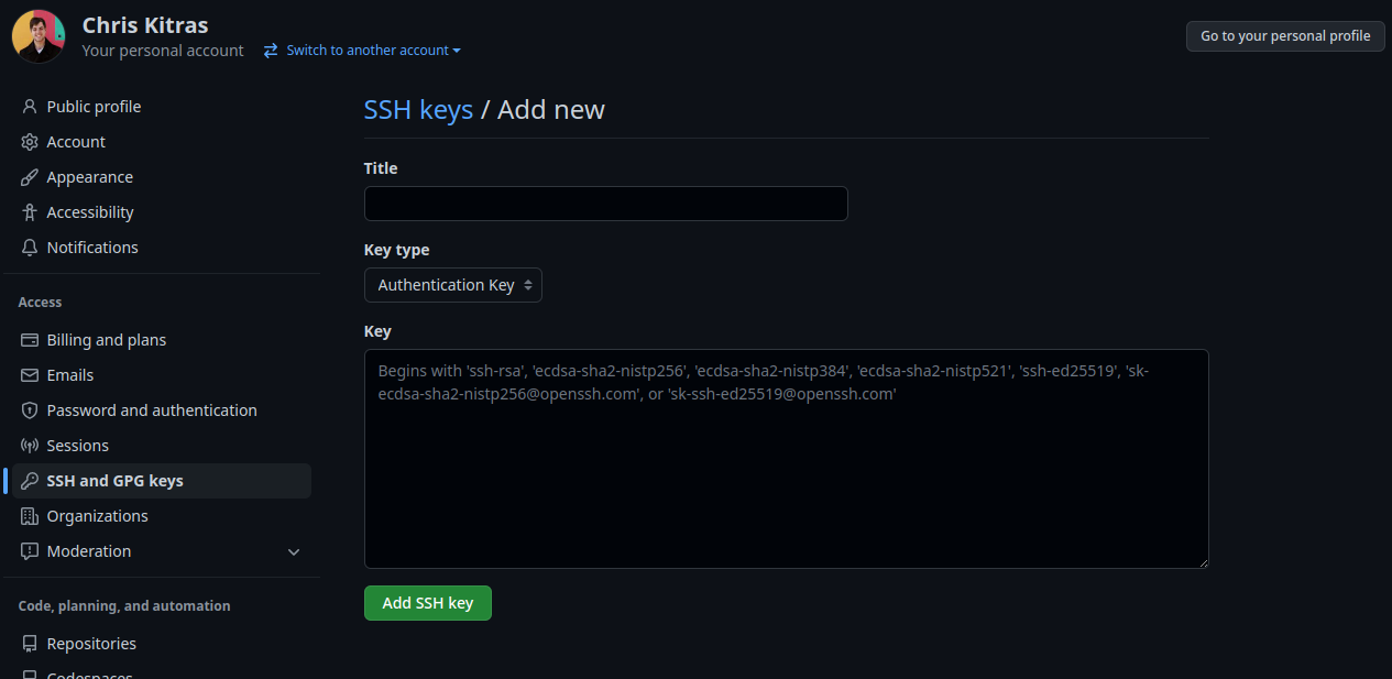
At the top of the page will be a big green button that says New SSH key. Click on this and then you should be taken to page like the one below:
-
Paste the contents that we copied into the Key box and feel free to add whatever value you desire into the Title. Make sure the dropdown menu for Key type is set to
Authentication Key. -
Finally, click Add SSH key and now your Pi Z2W should be able to talk to your GitHub account.
Setup GitHub Repository
Next, we need to ensure that git is installed on our Pi Z2W. This will be the terminal program that we use to communicate with GitHub to version control and submit our assignments.
-
If the terminal window on VSCode is not already open, press
Ctrl+`and then enter in the command:sudo apt install gitOnce
githas installed, we use this to download the first the repository (or code-base) for this lab. Since this lab requires no code to be written, the repository will be pretty uneventful. But remember these steps as future labs will use these steps to be set up. -
Click on the GitHub Classroom Link located on Learning Suite for the “Getting Started Lab” assignment. You will be taken to a page that asks you to accept the assignment. Accept it and then you will be transferred to a page with a link of your repository for this assignment. Click on that link and you should be brought to the default view of the repository.
-
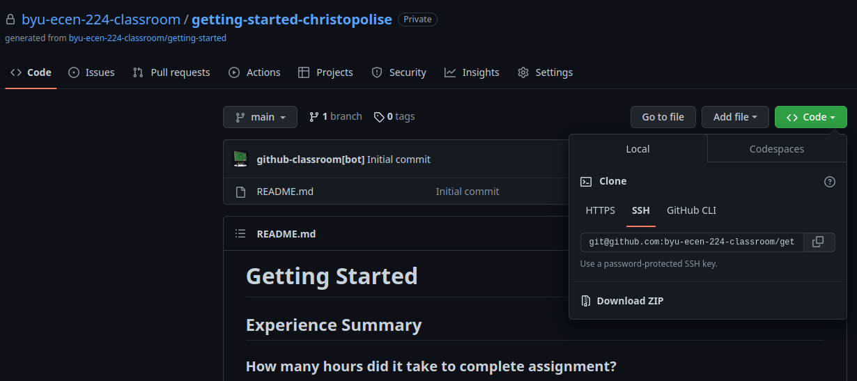
Click on the green button that says Code. Make sure you are on the SSH tab as shown below and copy the text in the box beneath.
-
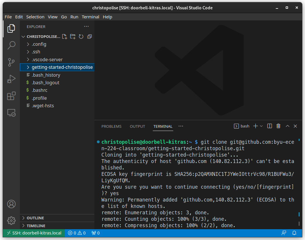
Back on the Pi Z2W’s terminal type in
git clone <GitHub Repo SSH URL>
This downloads a copy of the lab files from to your Pi Z2W. Since this lab is focused on setting up the Pi Z2W, there are no special files that you will need to interact with other than the README.md for your lab submission.
In future labs, any starter code or special resources for completing that lab will be included alongside that lab’s README.md.
Now it is time to start assembling the other parts of the kit. Shut down your Raspberry Pi with this command:
sudo shutdown -h now
The command sudo indicates to your Raspberry Pi that you want to perform the following command with admin-level priveleges. In this case, we are running the shutdown command, directing it to enter the -h halt state, and to do so immediately (now). You will need to provide your password when prompted. Be aware that unlike traditional password prompts, this one won’t show any characters as you type your password. After running this command, wait for the lights to stop blinking on your Pi before unplugging the PoE adapter.
Assemble the remaining kit
We will proceed to assemble the remaining components of your doorbell.
Your kit should look something like this:
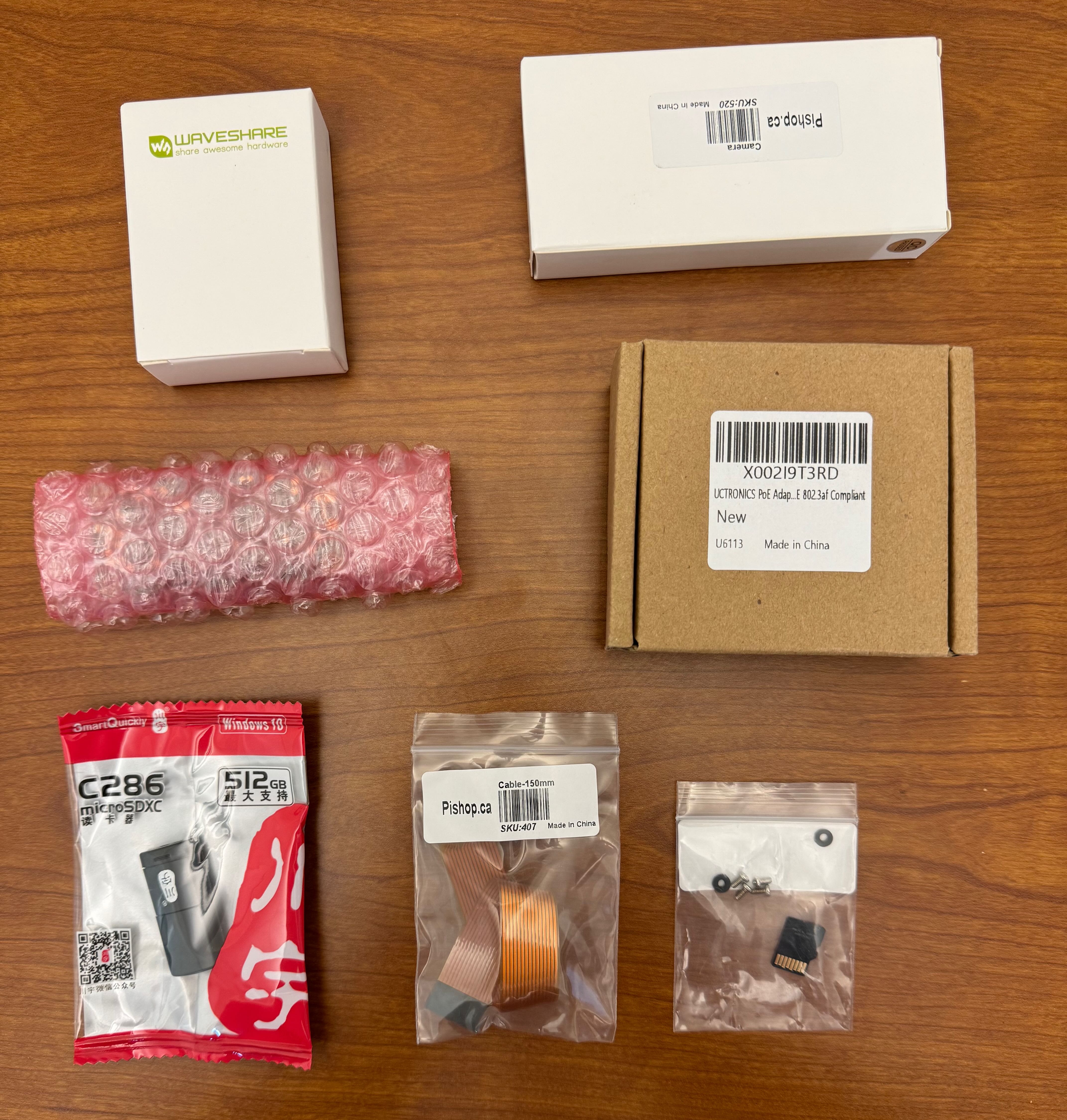
All parts still in packages
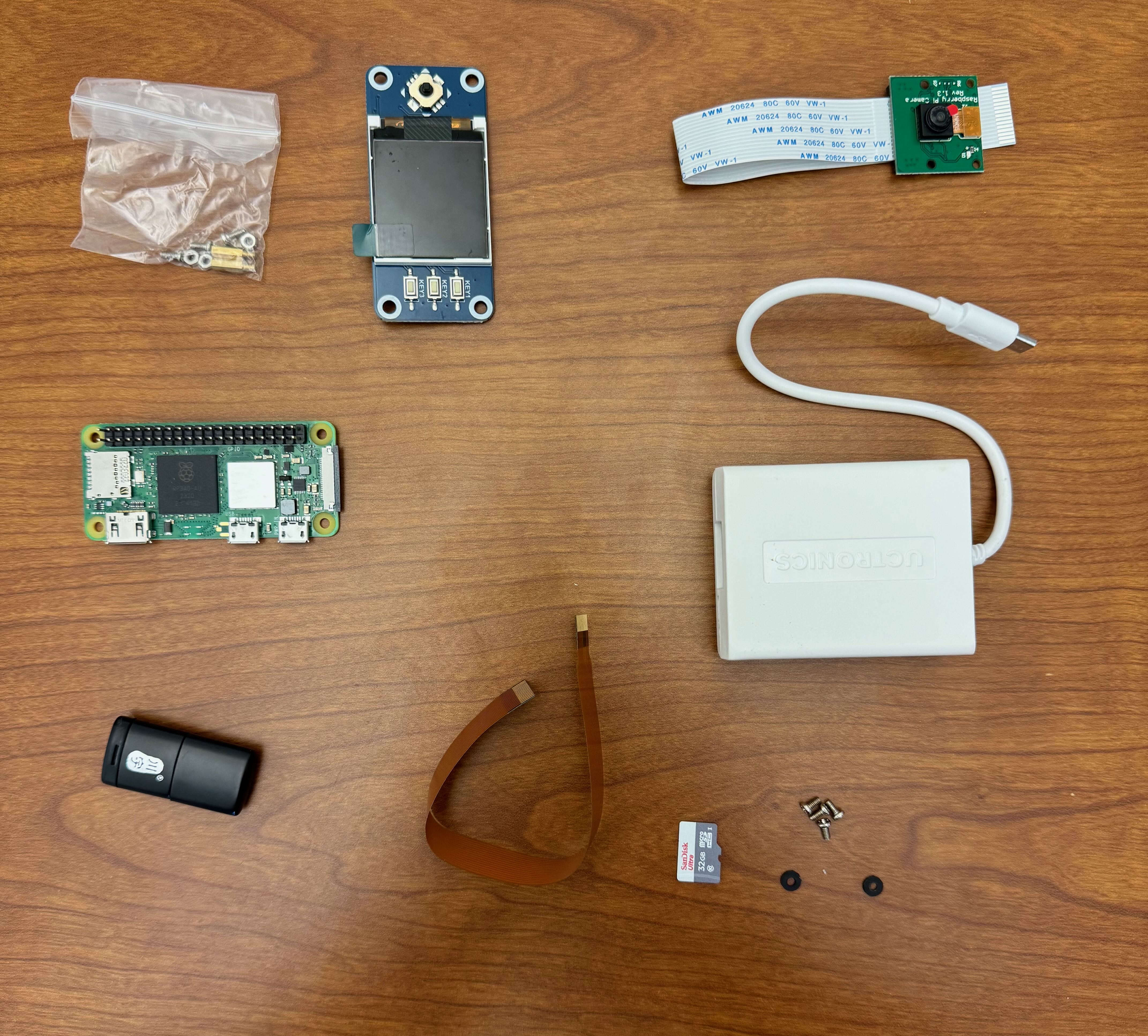
All parts unpacked
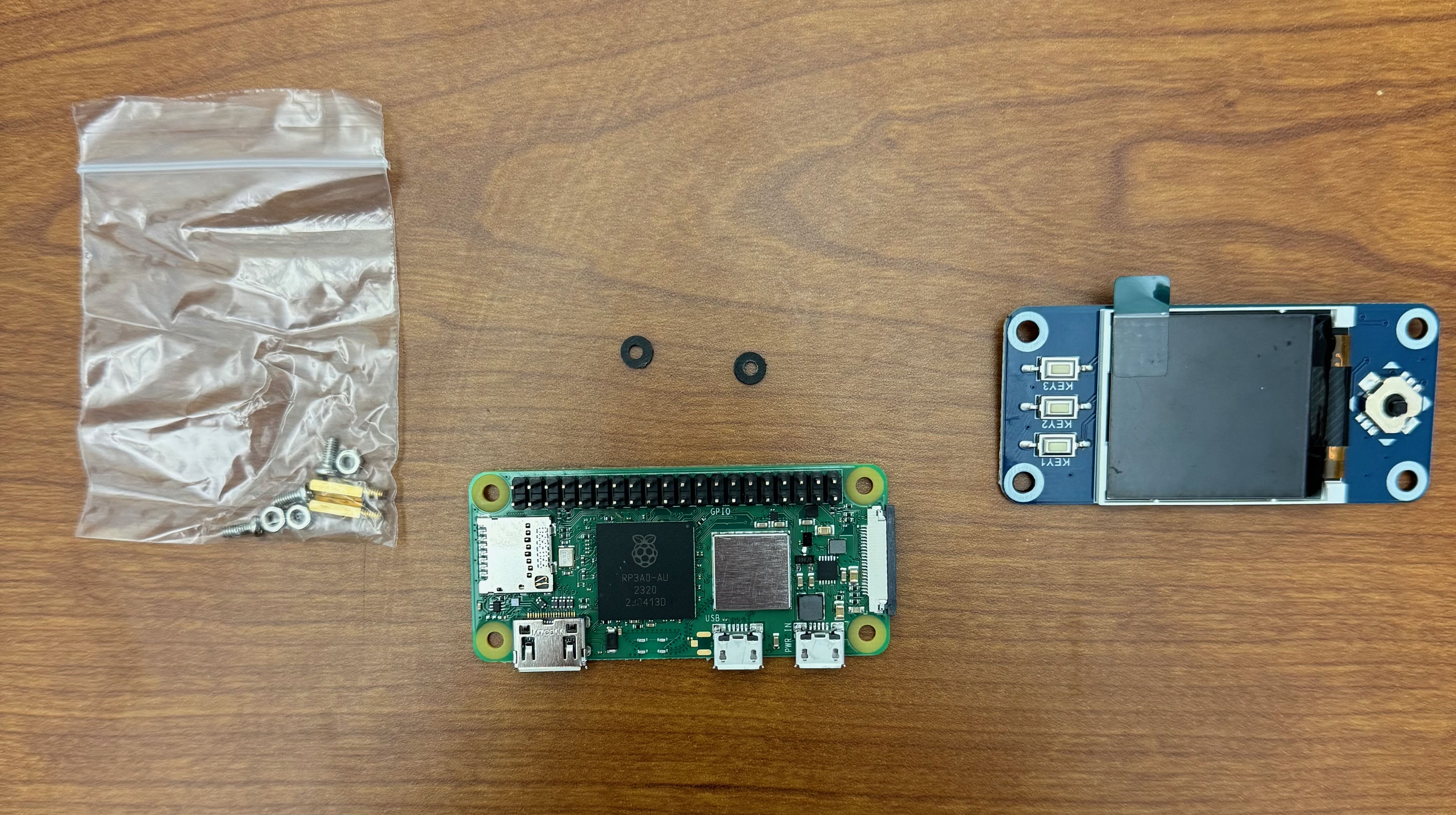
- Unpackage and prepare your display, standoffs, screws, nuts, and washers for assembly.
-
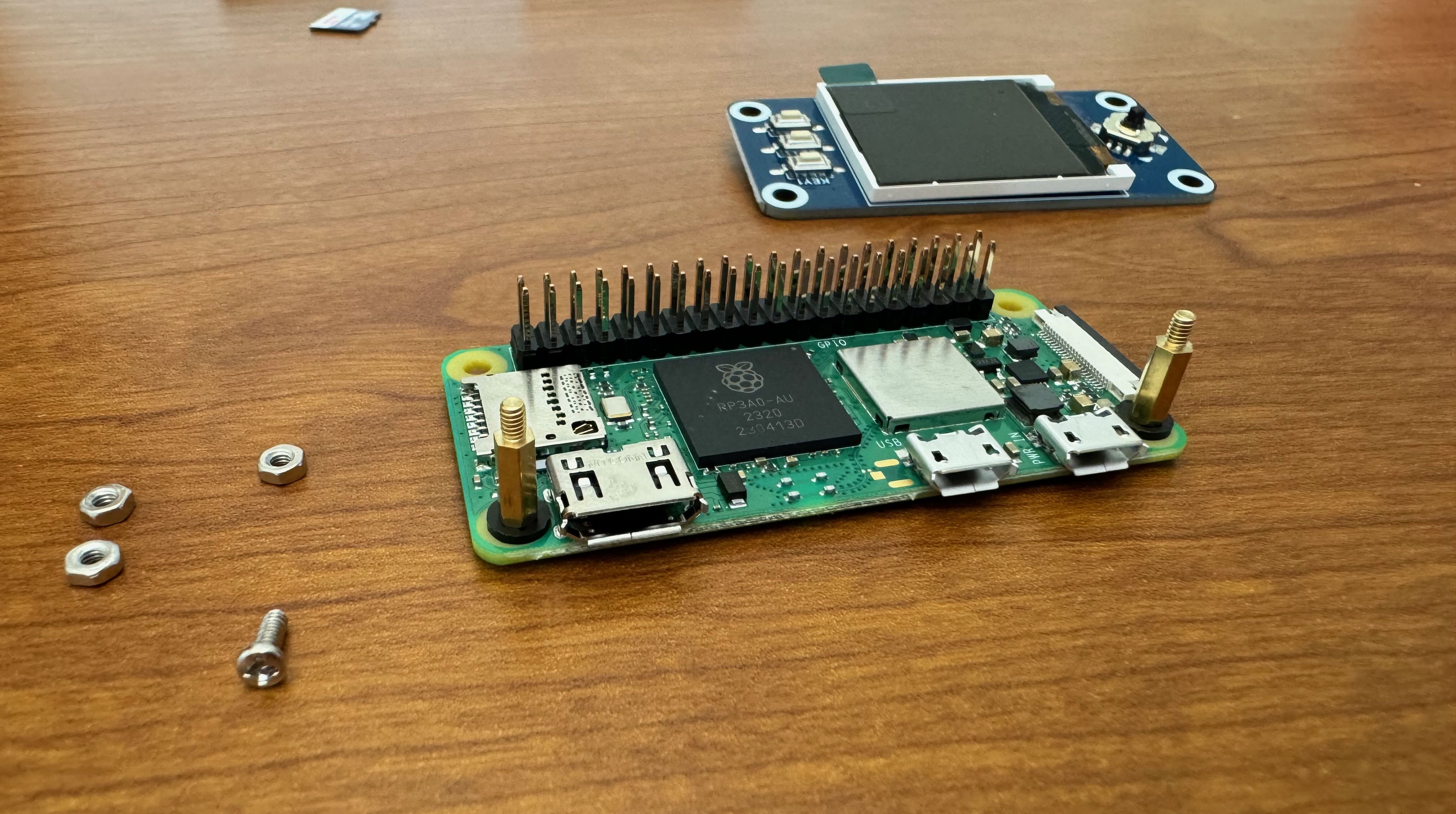
Put the screws through the holes of the Raspberry Pi Zero, on the side with the USB ports, so that the threads of the screw are on the same side of the PCB as the USBs.
-
Put the plastic washers on the screws, one washer per screw.
- Thread the brass standoffs onto the screws
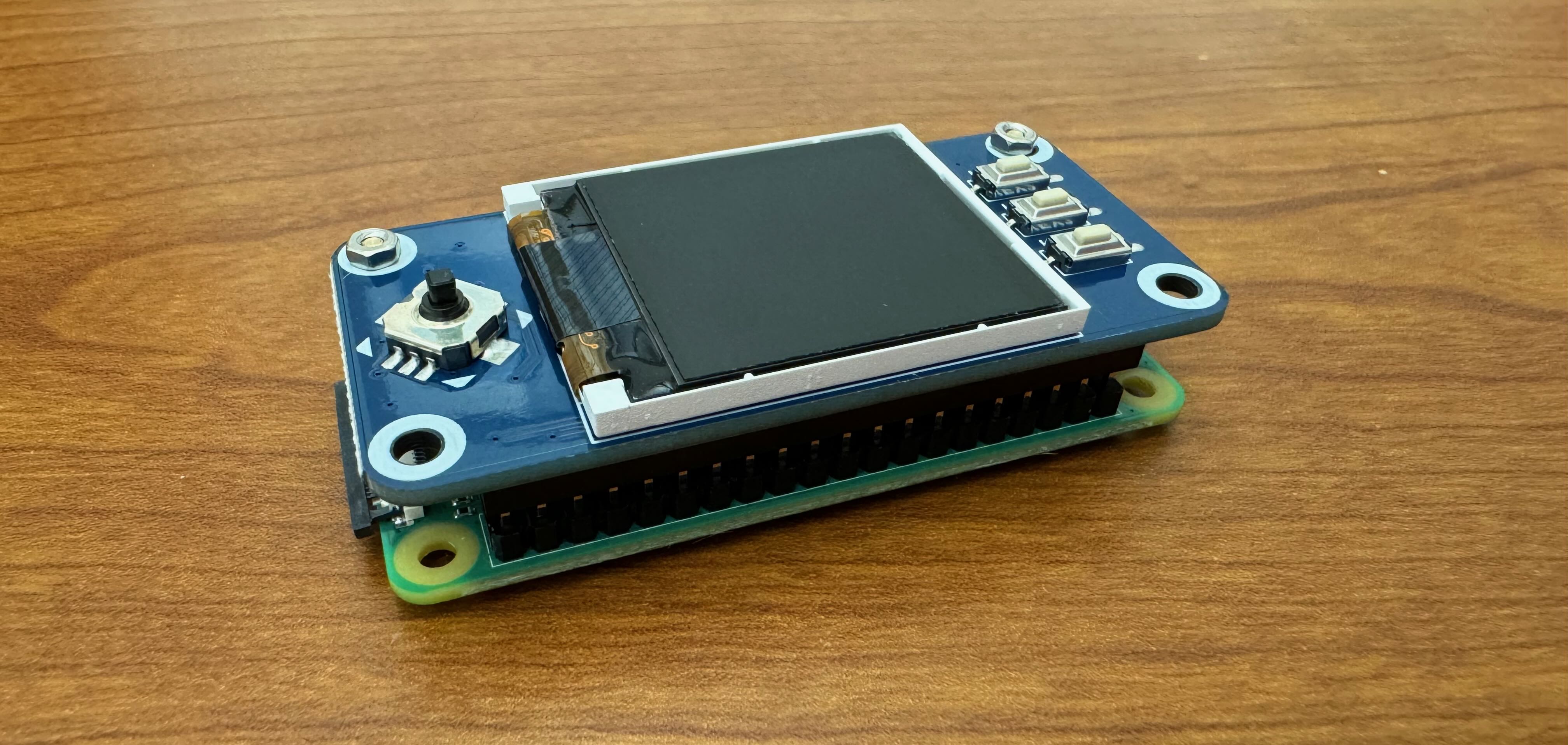
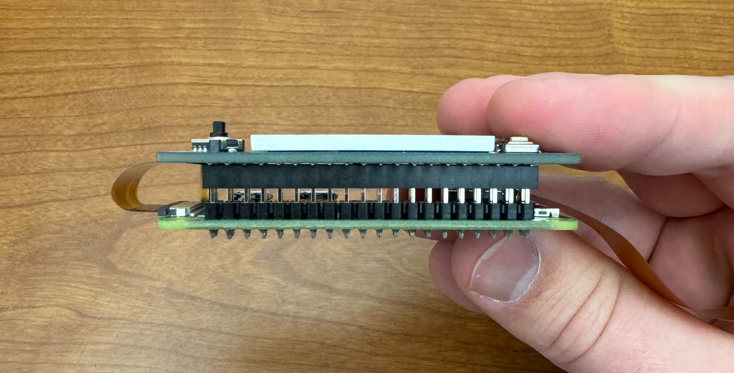
- Take the display PCB and line up the black plastic socket (on the back side of the PCB) with the metal pins sticking out of the Raspberry Pi. Gently press the display into the socket, making sure all pins seated into their corresponding holes without getting bent. Two of the holes on the display should have slid over the brass standoffs installed earlier.
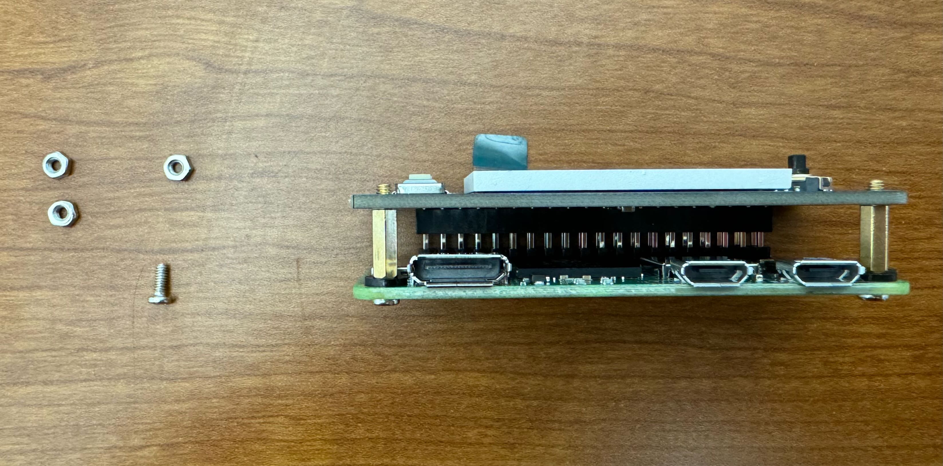
- Screw the nuts onto the standoffs to secure the display to the Raspberry Pi. Peel off the packaging protecting the surface of the display.
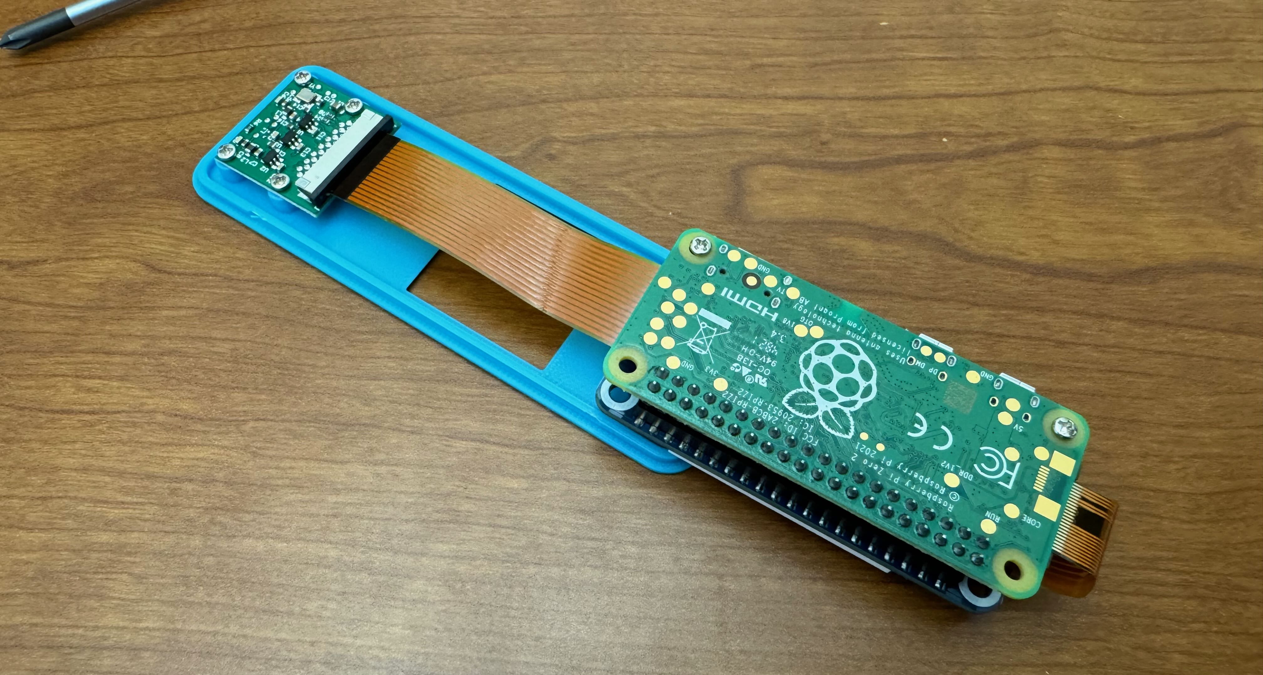
- Unpackage and prepare your camera kit and the case lid for assembly. Your kit came with two ribbon cables of different lengths. WE WILL BE USING THE BROWN RIBBON CABLE, NOT THE WHITE CABLE. Be aware that these ribbon cables are fragile.
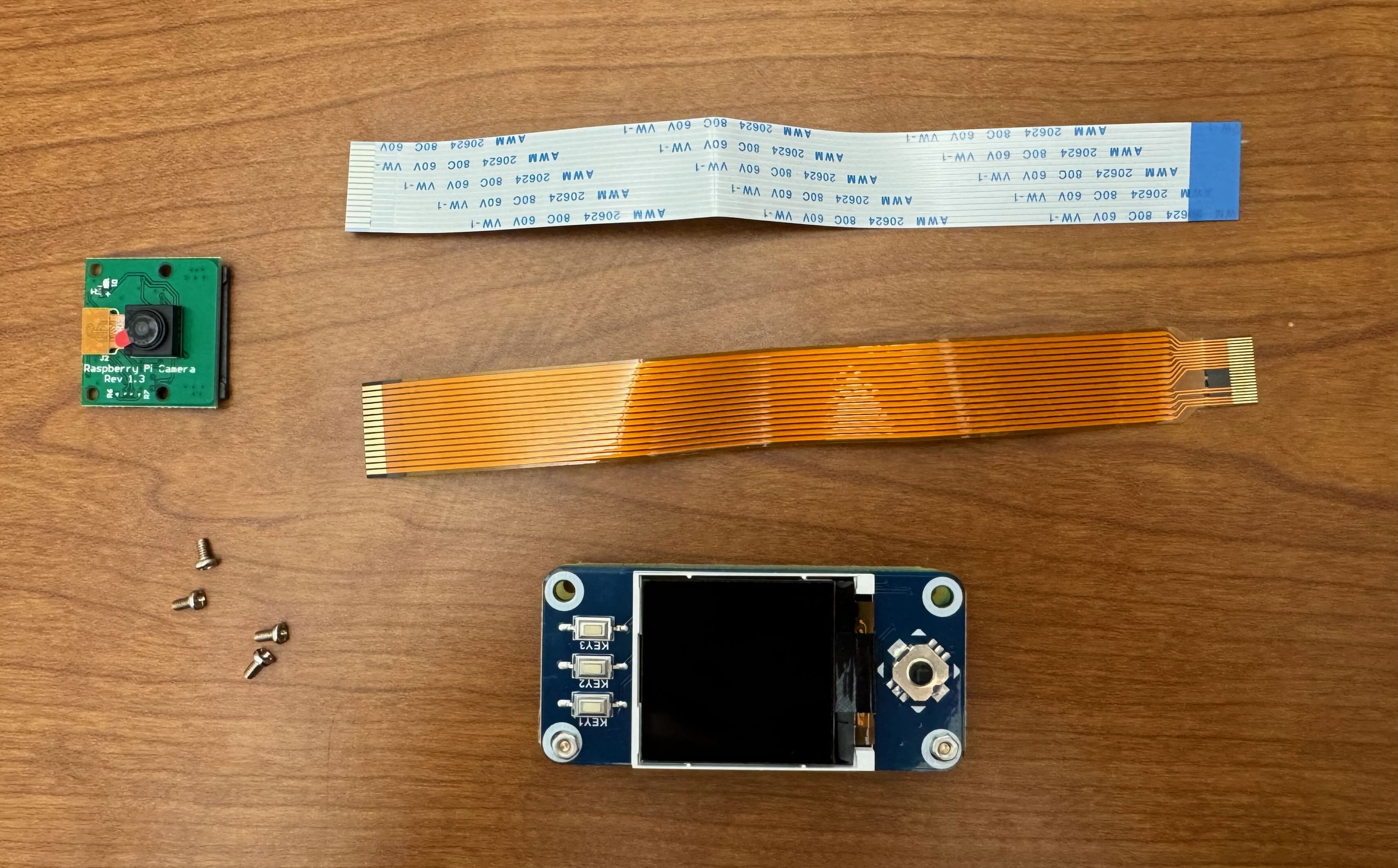
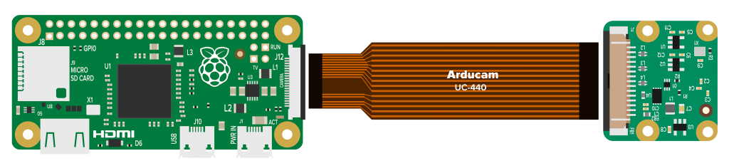
The Raspberry Pi Zero 2 W with the camera unit and connection cable. In this lab we will be using the larger cable and wrap it around the back of the Pi Z2W. - Familiarize yourself with the connector on your camera PCB. Note the orientation of the metal pins inside the connector and the plastic shroud along the edges. This shroud “locks” the connector, preventing the cable from being removed. Unlock it by gently pulling on the edges of the shroud until it slides out
- Insert the narrow end of the cable on the Raspberry Pi, making sure the copper contacts on the ribbon are oriented correctly. Note - in this image, the connector is in the “locked” state
- Gently wrap the ribbon cable between the Raspberry Pi and the display HAT. Be careful not to bend the metal part of the ribbon cable that is coming out of the Raspberry Pi.
- Insert the wider end of the cable into the camera module, making sure the copper contacts on the ribbon are oriented correctly. Note - in this image, the connector is in the “unlocked” state. Make sure to lock the connector once you have installed the ribbon.
-
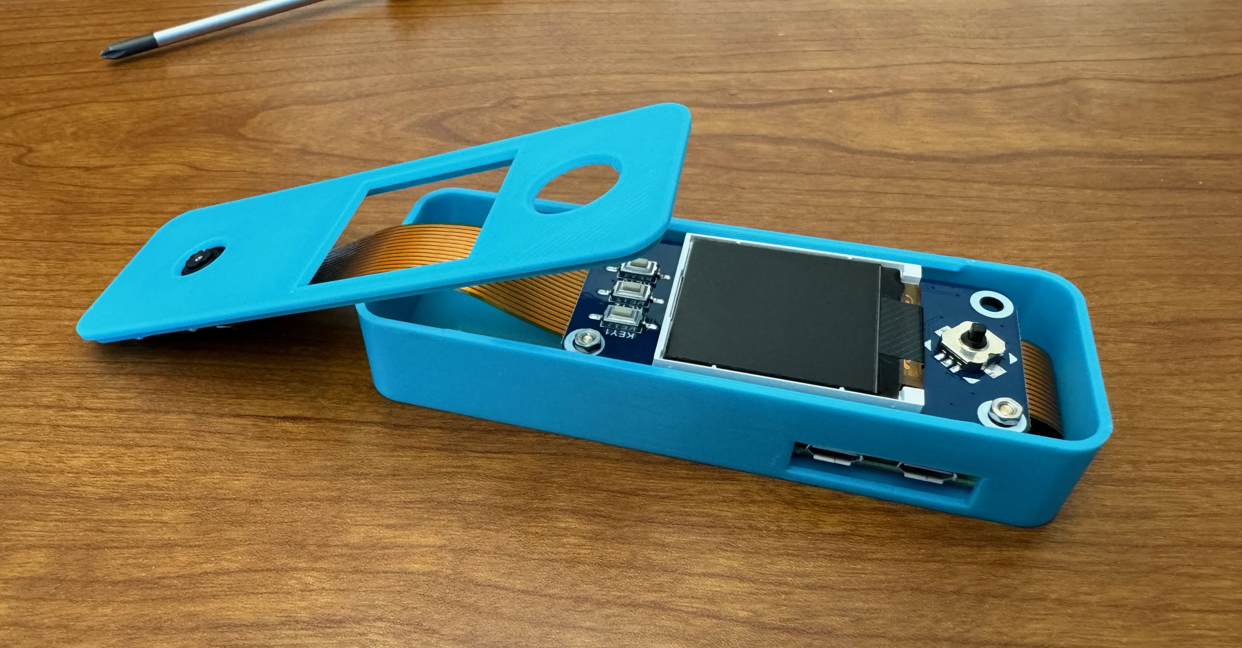
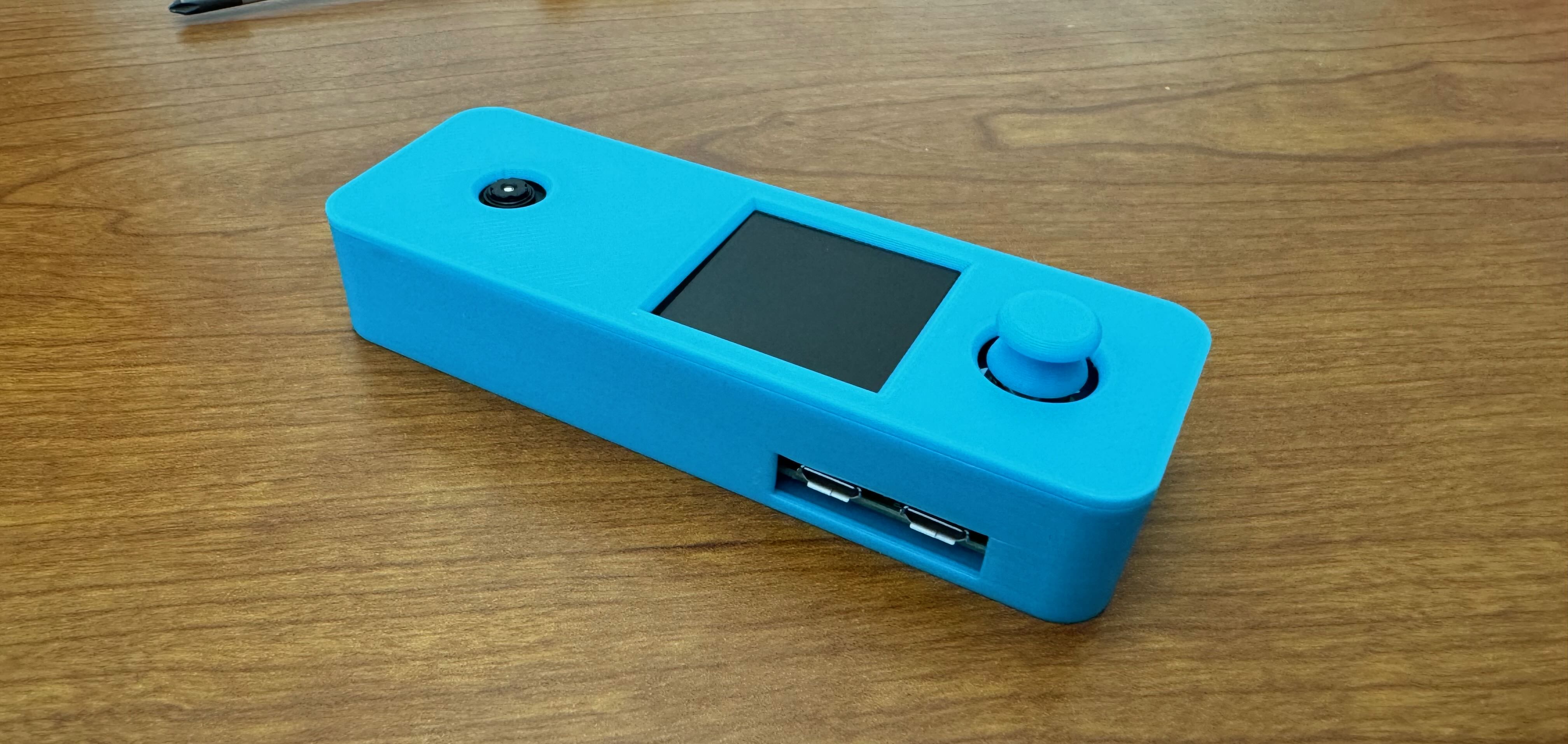
In this lab, you were also given a 3D printed enclosure for your Pi Z2W kit.
Doorbell case 3D printed file. You will need to attach the camera module to the standoffs on the lid. Note that the button in this file is not included in the case you will receive in this lab. As visible in the 3D model above, there are several components that comprise this enclosure. The top of the case is the long, rectangular part with holes for the camera, LCD screen, and button respectively.
- You’ll notice that around the camera holes are four standoffs. These standoffs correspond to the holes in the camera module mentioned in the section before. Remove the packaging film covering the lense of your camera, then mount the camera board to the lid of the case using the 4 screws. It is easiest to do this with the Raspberry Pi face down.
- Insert the Raspberry Pi into the case. Make sure the remaining 2 empty holes on the Raspberry Pi line up with the pegs in the case.
- Tuck the extra slack of the ribbon cable under the camera. Be careful not to pinch the ribbon cable.
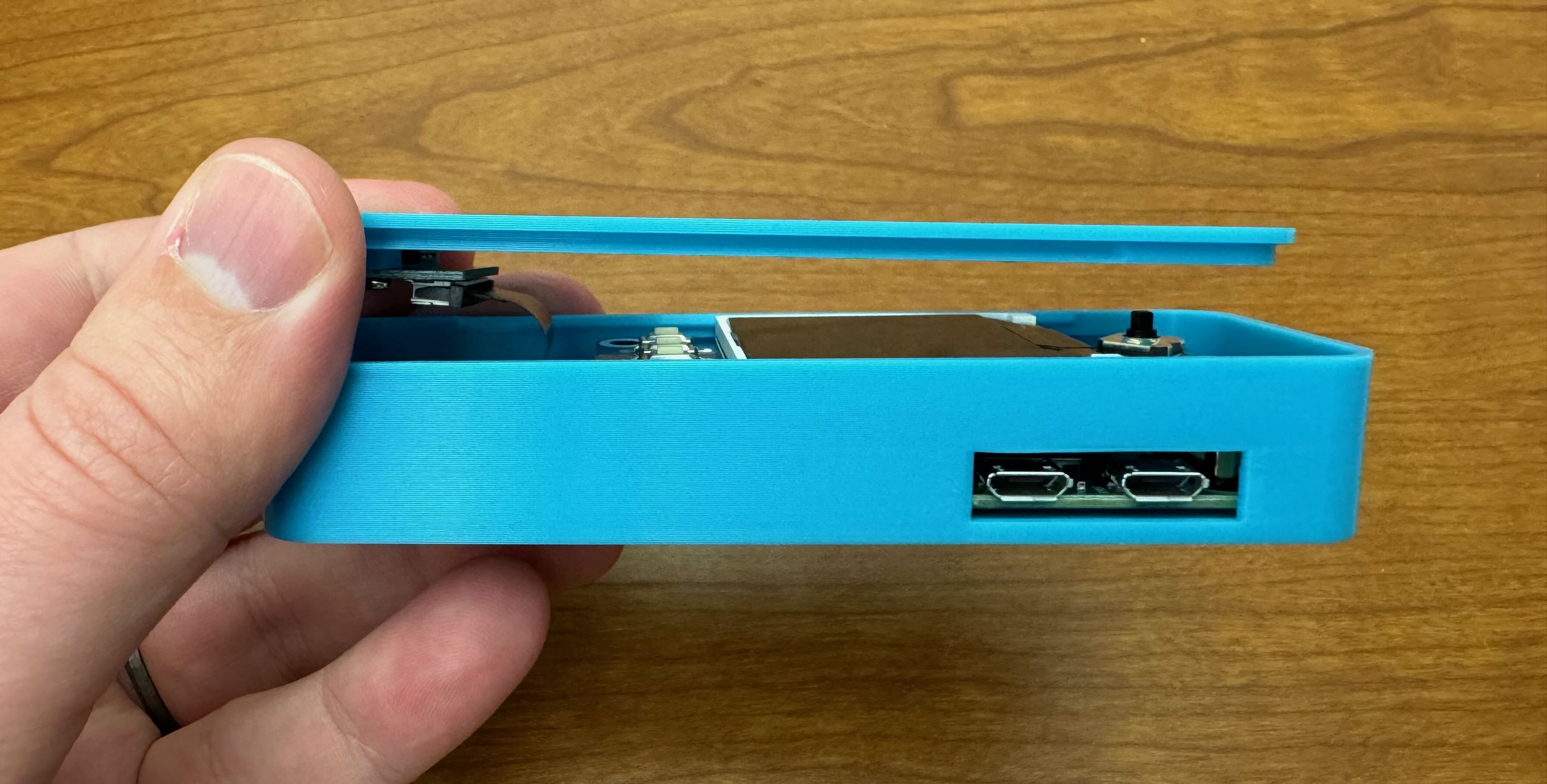
- Snap the lid onto the bottom of the case.
- Slide the 3D button on the square peg of the display HAT.
Details about the display and camera hardware will be presented in future labs.
Turn your Pi Z2W on by plugging in your PoE adapter and re-connect to the Pi over SSH like we did earlier.
Lab Submission
-
Answer the questions in the
README.md. -
To successfully submit your lab, you will need to follow the instructions in the Lab Setup page, especially the Committing and Pushing Files section.