Table of Contents
Objectives
- Become familiar with the tools used for this class
- Be able to gain access remotely to the Raspberry Pi Zero 2 W
- Begin building skills needed to construct the doorbell
Introduction
This lab, like all others in the course, requires the ECEn 225 Lab Kit. If you do not have a kit, purchase one from the Experiential Learning Center (The Shop) in CB 416.
This course uses the Raspberry Pi Zero 2 W (Pi Z2W) to teach core computing principles. In this lab, you will prepare this single-board computer to support all course activities.
This lab consists of four parts:
- Flash and configure the Pi Z2W with Linux
- Gain remote access to the Pi Z2W over SSH
- Set up a C development environment
- Assemble the hardware components into a doorbell
Procedure
Part 1: Flash and Configure your PI Z2W
Setting up the SD Card
To use the Pi Z2W, install an operating system on its SD card. An operating system (OS) is a set of programs that allows users to interact with hardware. Windows, macOS, and Linux are examples of operating systems, each tailored to different platforms. Linux offers a variety of distributions suited for different needs.
This lab uses Raspberry Pi OS, a Linux distribution designed for Raspberry Pi devices.
Normally, you would use the Raspberry Pi Imager tool to install the OS. However, due to lab machine limitations, follow this alternative method.
-
Open a terminal on your lab machine using the Activities menu or the shortcut
Ctrl+Alt+T. Download and run the imaging script by entering:wget https://byu-cpe.github.io/ecen224/assets/scripts/imager.sh chmod +x imager.sh ./imager.sh(Use
Ctrl+Shift+Vto paste into the terminal after copying the command.) -
Wait for the script to complete. It may take a long time; it will prompt you for input during the process.
-
After the script finishes, remove the SD card from the computer and insert it into the SD card slot of the Pi Z2W.
Assemble the Display
Your kit should look something like this:
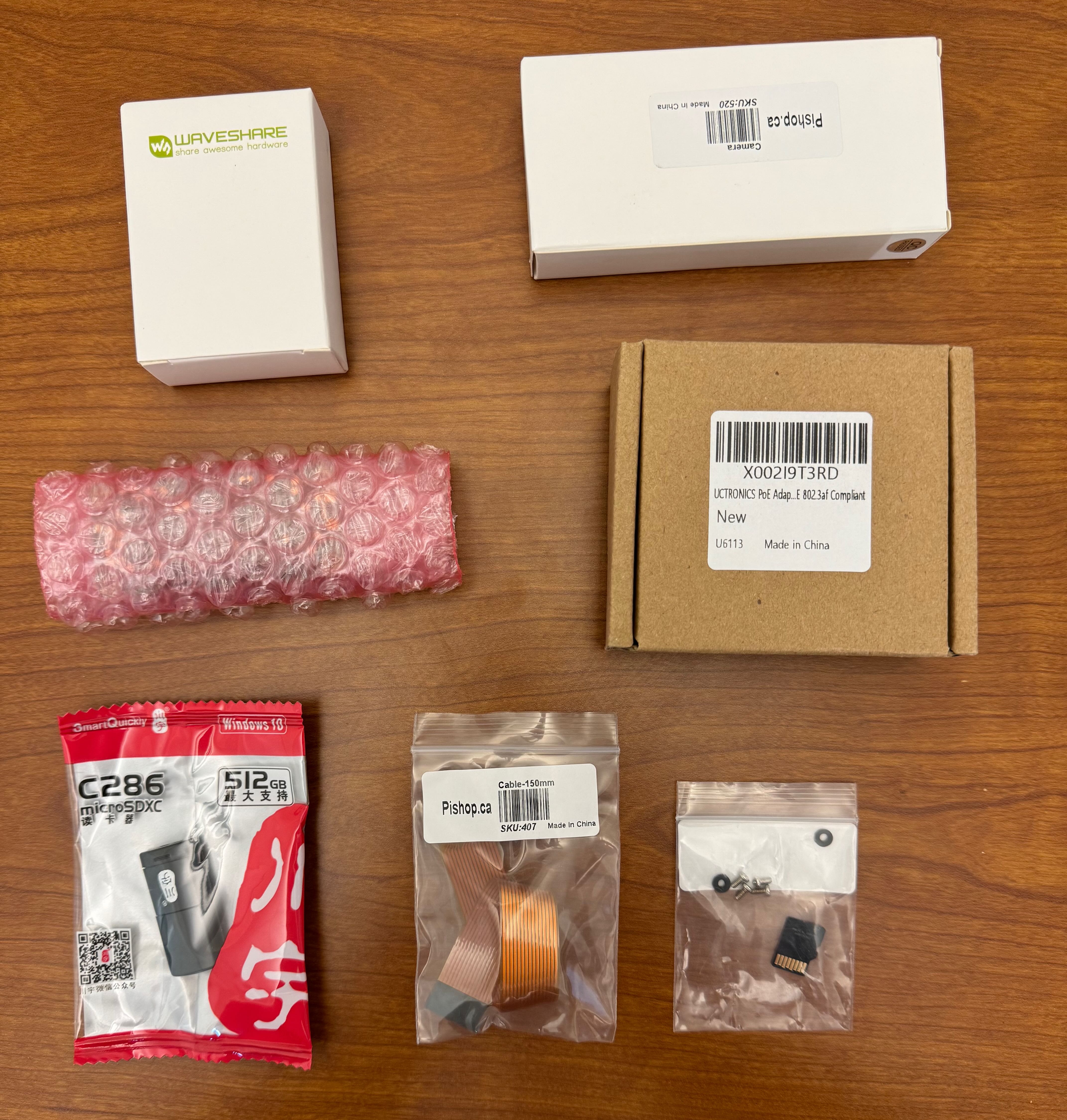
All parts still in packages
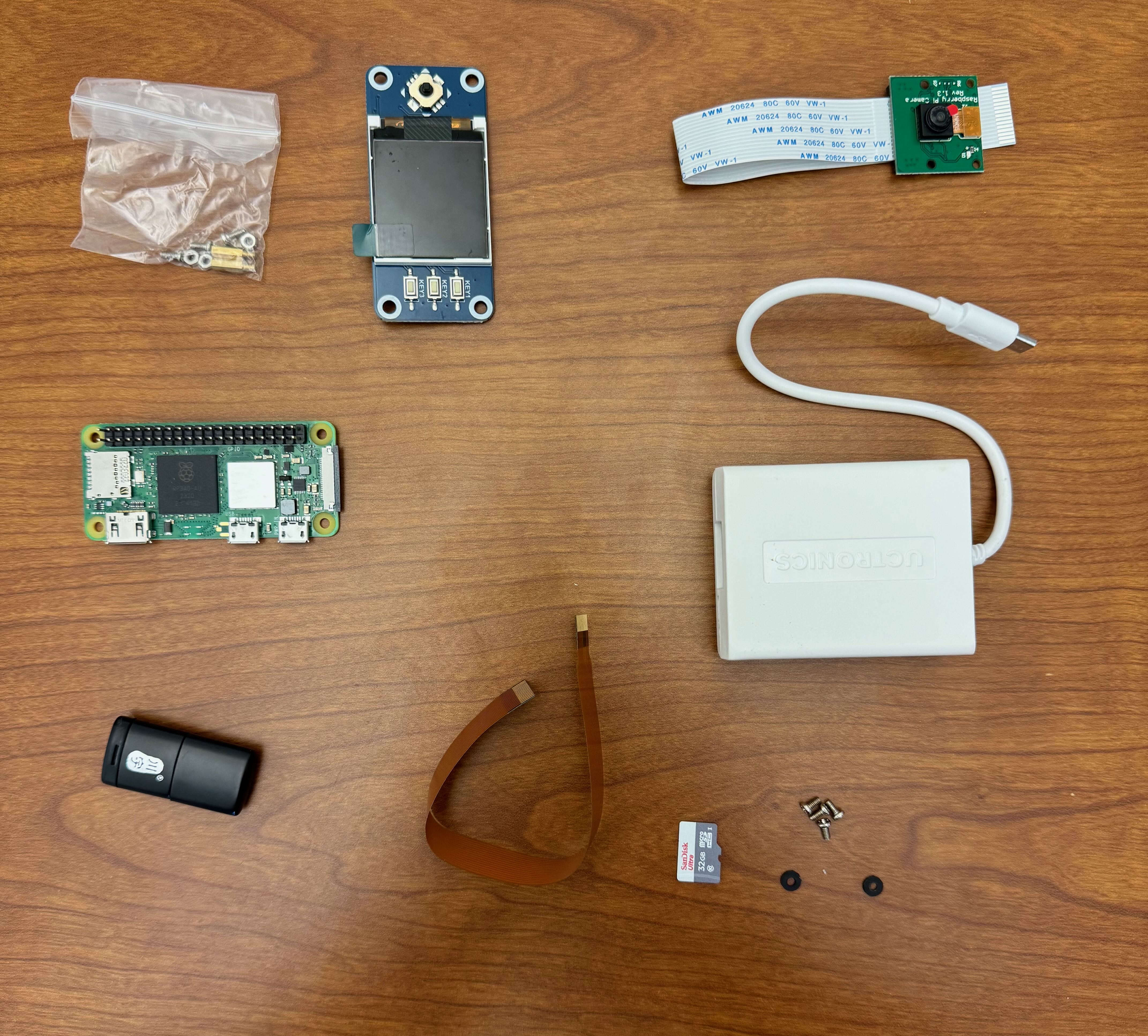
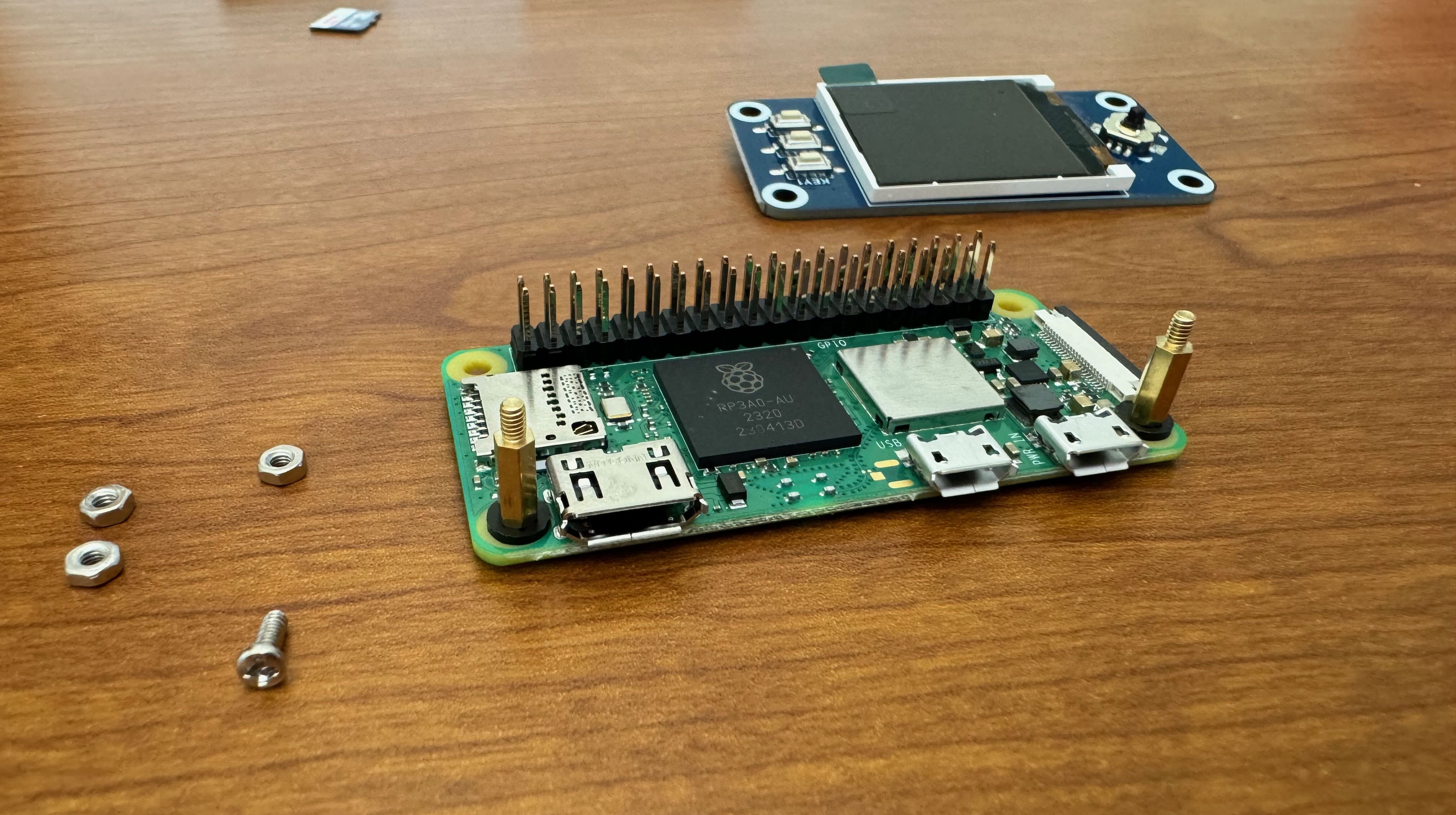
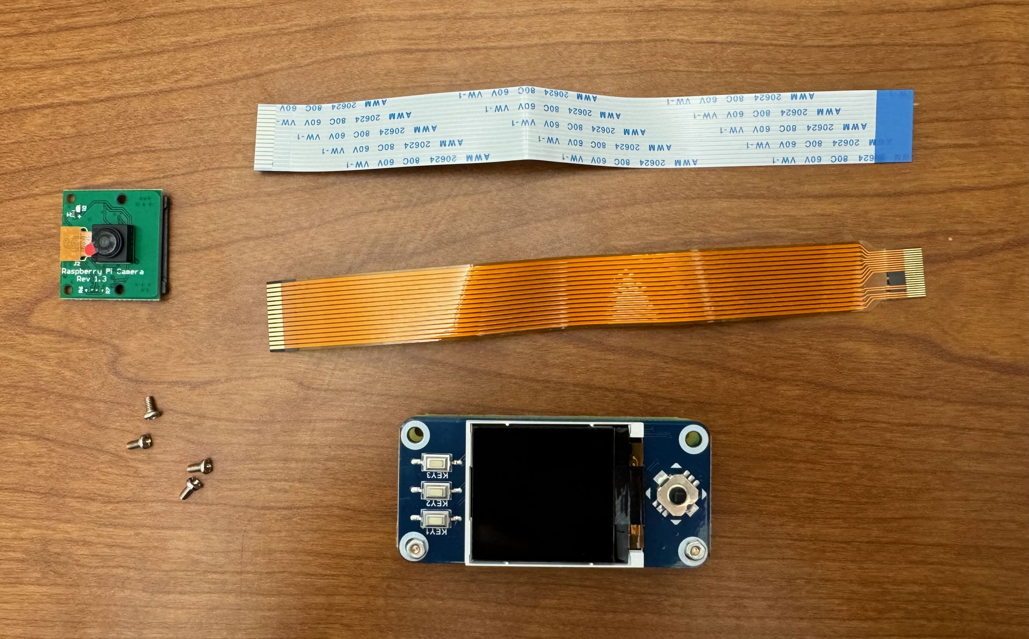
All parts unpacked
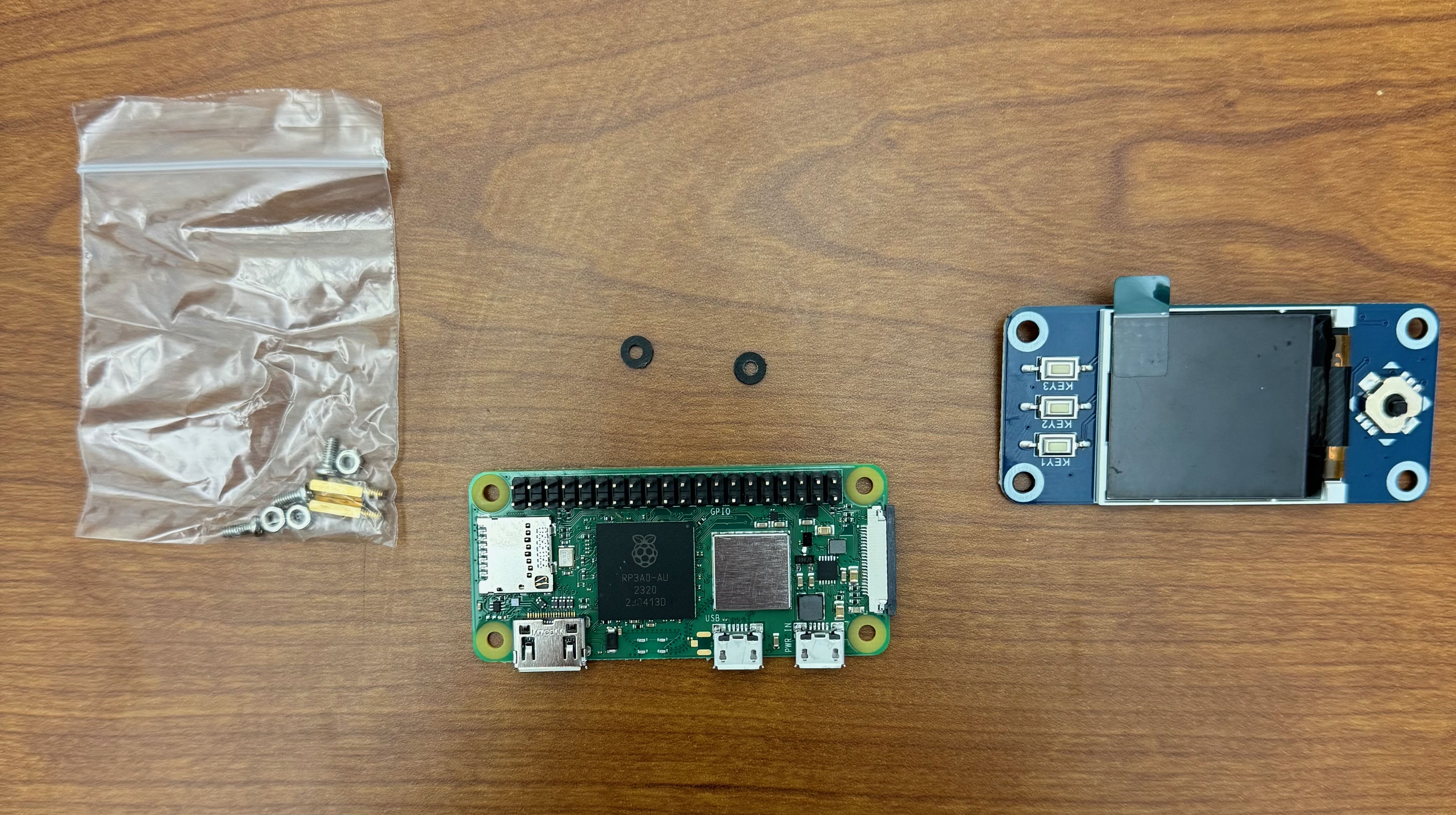
In order to see that your Z2W was configured correctly, we need to assemble the display. Assemble the display portion of your doorbell kit using the following steps:
-
Unpackage the display, standoffs, screws, nuts, and washers.
-
Insert the screws through the Raspberry Pi Zero from the side with the USB ports, so the threads protrude on the same side as the USB connectors.
-
Place one plastic washer on each screw.
-
Thread a brass standoff onto each screw.
-
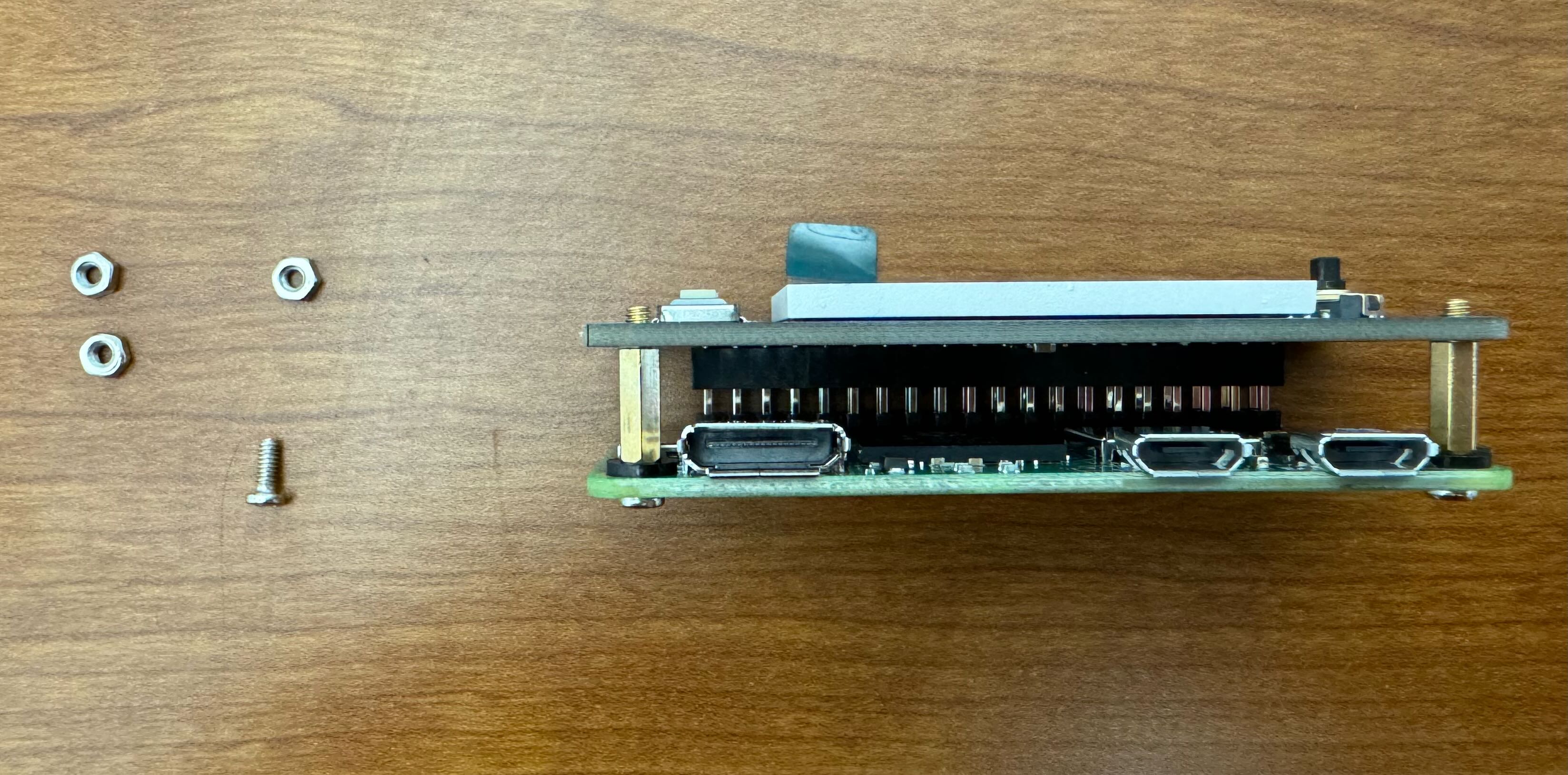
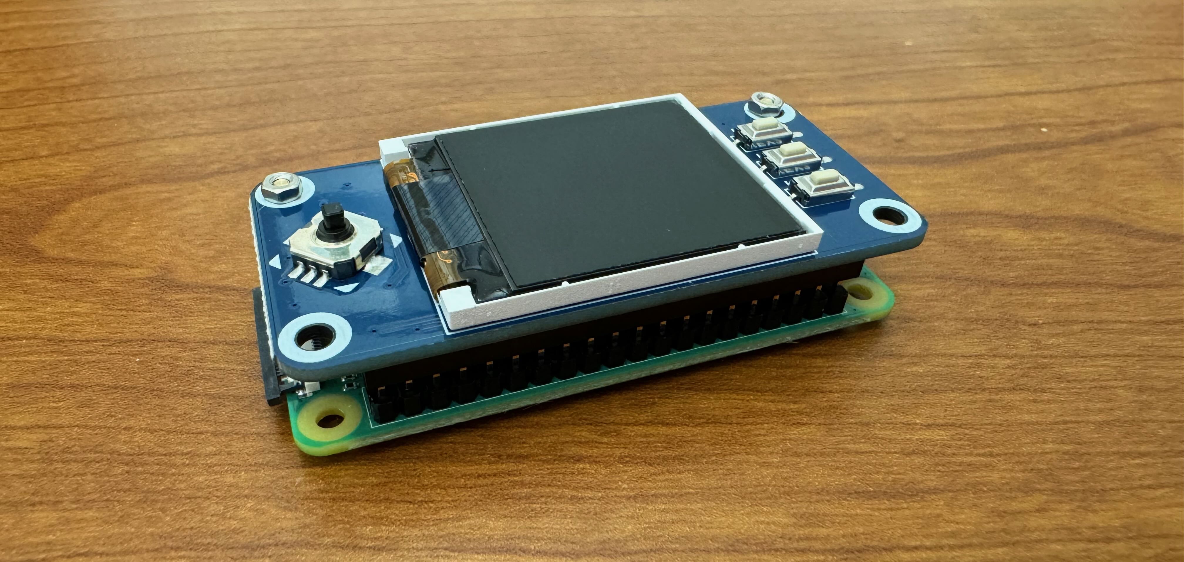
Align the black plastic socket on the back of the display PCB with the Raspberry Pi’s GPIO pins. Press the display gently into place, ensuring all pins seat correctly. The two mounting holes on the display should align with the standoffs.
-
Secure the display by screwing the nuts onto the standoffs. Remove the protective film from the display surface.
-
Set aside the remaining parts of the kit. We will come back to them in Part 4.
Part 2: Connect to Pi Z2W over SSH
Use the Power over Ethernet (PoE) adapters—the white bricks at each lab computer—to power the Pi Z2W. PoE transmits both power and internet through a single Ethernet cable, eliminating the need for separate power cables. While not all Ethernet ports support PoE, every port in the Digital Lab does.
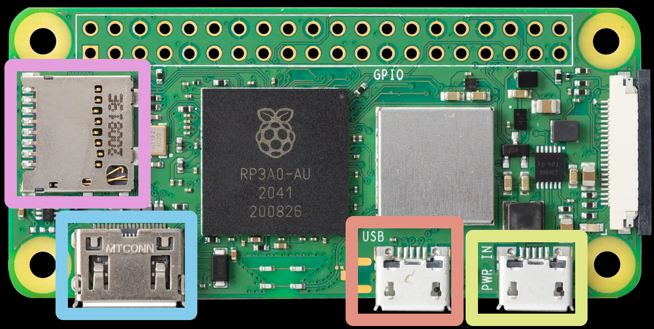
To power the Pi Z2W, unplug the Ethernet cable from the PoE adapter. Connect the adapter to the first micro USB port (labeled “USB” and located on the left in the figure at the beginning of this lab). Reconnect the Ethernet cable to the PoE adapter. This sequence ensures the network assigns an IP address to the Pi over the Ethernet connection.
Allow up to three minutes for the Pi to boot. When the system is ready, the display will show a blue screen with two addresses: the localhost address (127.0.0.1) and an assigned IP address in the form 10.32.X.X. If the IP address does not appear, unplug the Ethernet cable from the PoE adapter and reconnect it. If the issue continues, notify a TA.
With Raspberry Pi OS Lite installed and the Pi Z2W connected to the lab network, you can now access it remotely using ssh. This allows you to log into the Pi Z2W from another machine, such as the lab computer.
-
Verify that your lab machine can detect the Pi Z2W. Open the terminal (
Ctrl+Alt+T) and run:# replace NETID with your NetID ping doorbell-NETID.localIf the output shows:
ping: doorbell-NETID.local: Name or service not knownthen the Pi Z2W is not connected to the lab network. Confirm the Ethernet cable is connected properly to both the correct port on the Pi and the wall jack. Wait several minutes before retrying. If it still fails, seek assistance.
If the output shows:
 PING doorbell-NETID.local (192.168.86.48) 56(84) bytes of data.
 64 bytes from doorbell-NETID.local (192.168.86.48): icmp_seq=1 ttl=64 time=95.7 ms
 ...
 # it will keep pinging until you stop it
press
Ctrl+Cto stop the ping. Your machine can now communicate with the Pi Z2W. -
Log in via SSH:
ssh NETID@doorbell-NETID.localEnter the password set earlier. Nothing will appear as you type. Press
Enterwhen finished. -
When prompted to confirm trust in the remote machine, type
yes. -
Once logged in, confirm you are in the Pi by checking the prompt:
NETID@doorbell-NETID:~$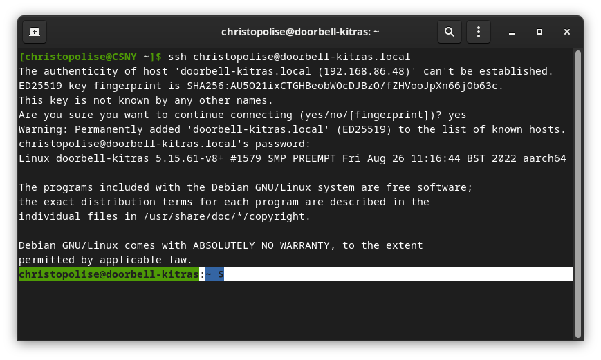
-
Download the setup script to install required tools:
wget https://byu-cpe.github.io/ecen224/assets/scripts/install.sh -
Make the script executable:
chmod +x install.sh -
Execute the script:
./install.shYou will see various outputs in the terminal as packages install. When prompted for your password, enter the Pi Z2W password you set earlier.
-
Reboot the Pi Z2W:
sudo rebootThis will disconnect your Pi Z2W from the lab machine in the process. You will reconnect to it in the next part.
Part 3: Set Up your Development Environment
Setting Up VSCode on the Z2W
-
Launch VSCode from the Activities menu.
-
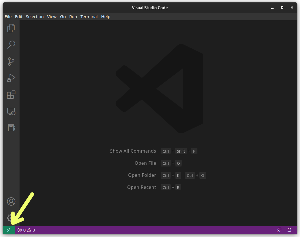
Check the lower-left corner of the VSCode window for the green icon:
-
If the icon is missing, install the Remote - SSH extension:
- Click the extensions icon:

- Search for
Remote - SSH - Click Install on the extension authored by Microsoft
- Click the extensions icon:
-
After installation, click the green icon in the lower-left.
-
Select Connect to Host > Add New SSH Host.
-
Enter the full SSH command you used in Part 2:
ssh NETID@doorbell-NETID.local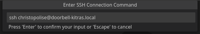
-
Save to your local SSH config (e.g.,
/home/...or/fsi/...):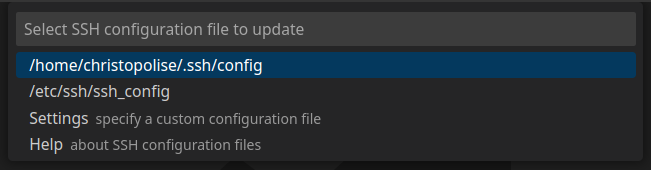
-
Click the Remote SSH icon again, then choose
Connect to Hostand then click thedoorbell-NETID.localentry you just set up. -
A new window opens. Enter your Pi Z2W password. Wait for some dependencies to install if prompted.
-
Click the file explorer icon in the left sidebar:

-
Click Open Folder, then OK. This opens the Pi Z2W home directory in VSCode.
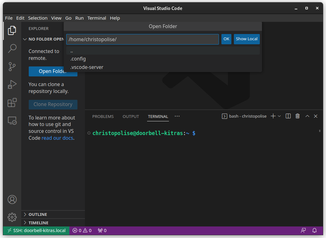
You can now access and edit files on your Pi Z2W directly through VSCode.
Set Up GitHub and Clone your Starter Labs
All labs require code to be cloned from and uploaded to GitHub. Create a Github account at github.com/join if you don’t already have one. You may use your personal account if you preferr.
To configure GitHub on your Pi Z2W:
- Navigate to the
GitHub Setuptab. - Complete all steps in the First Time Setup section. This includes:
- Setting your username and email in git
- Generating an SSH key
- Adding the SSH key to your GitHub account
- Verifying the SSH connection to GitHub
- Proceed to the Cloning A Repository section.
- Follow the instructions to clone your
Starter Labsrepository.- The GitHub Classroom link is provided in Learning Suite under the schedule entry for Lab 1.
After cloning, the code will be available in your Pi Z2W’s filesystem for development and submission.
Part 4: Assemble the Remaining Kit
Next we will proceed to assemble the remaining components of your doorbell kit.
-
Turn off your Raspberry Pi Zero 2 W using the command:
sudo shutdown nowAnd wait for the green LED to turn off. After that, unplug the PoE adapter from the micro USB port.
-
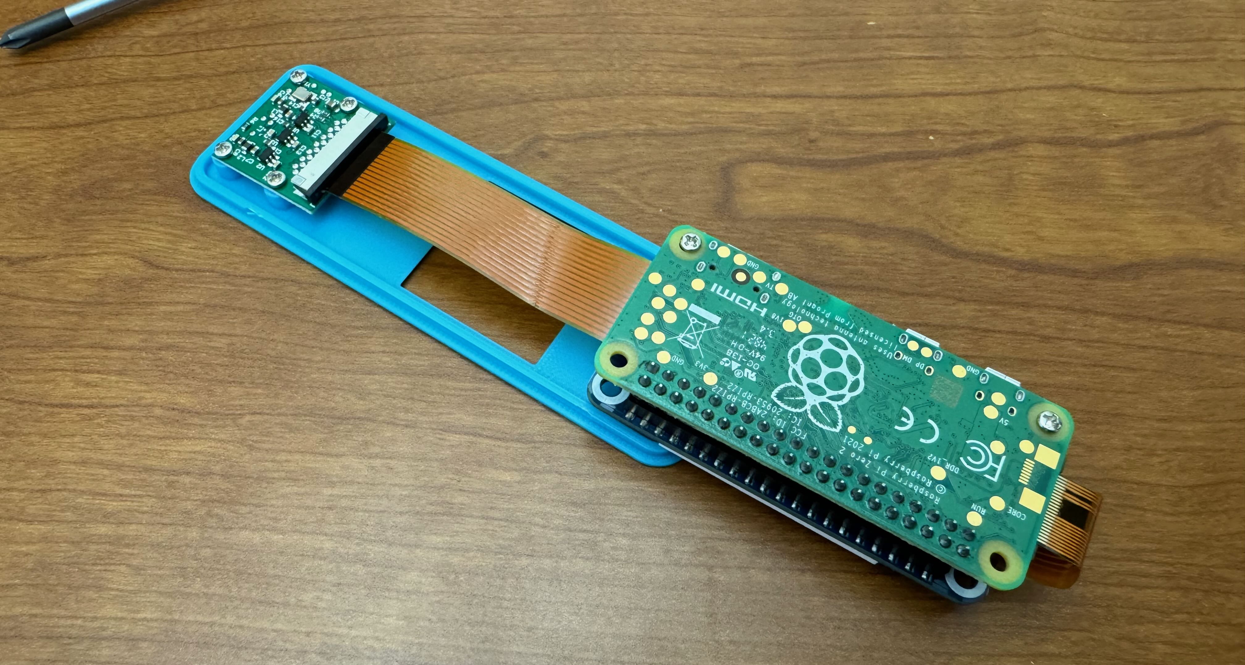
Unpack the camera kit and case lid. Use the brown ribbon cable (not the white one). The ribbon cables are fragile.Handle them with care, and do not crease or bend them extremely sharply.
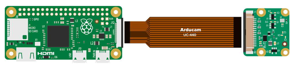
The Raspberry Pi Zero 2 W with the camera unit and connection cable. In this lab we will be using the larger cable and wrap it around the back of the Pi Z2W. -
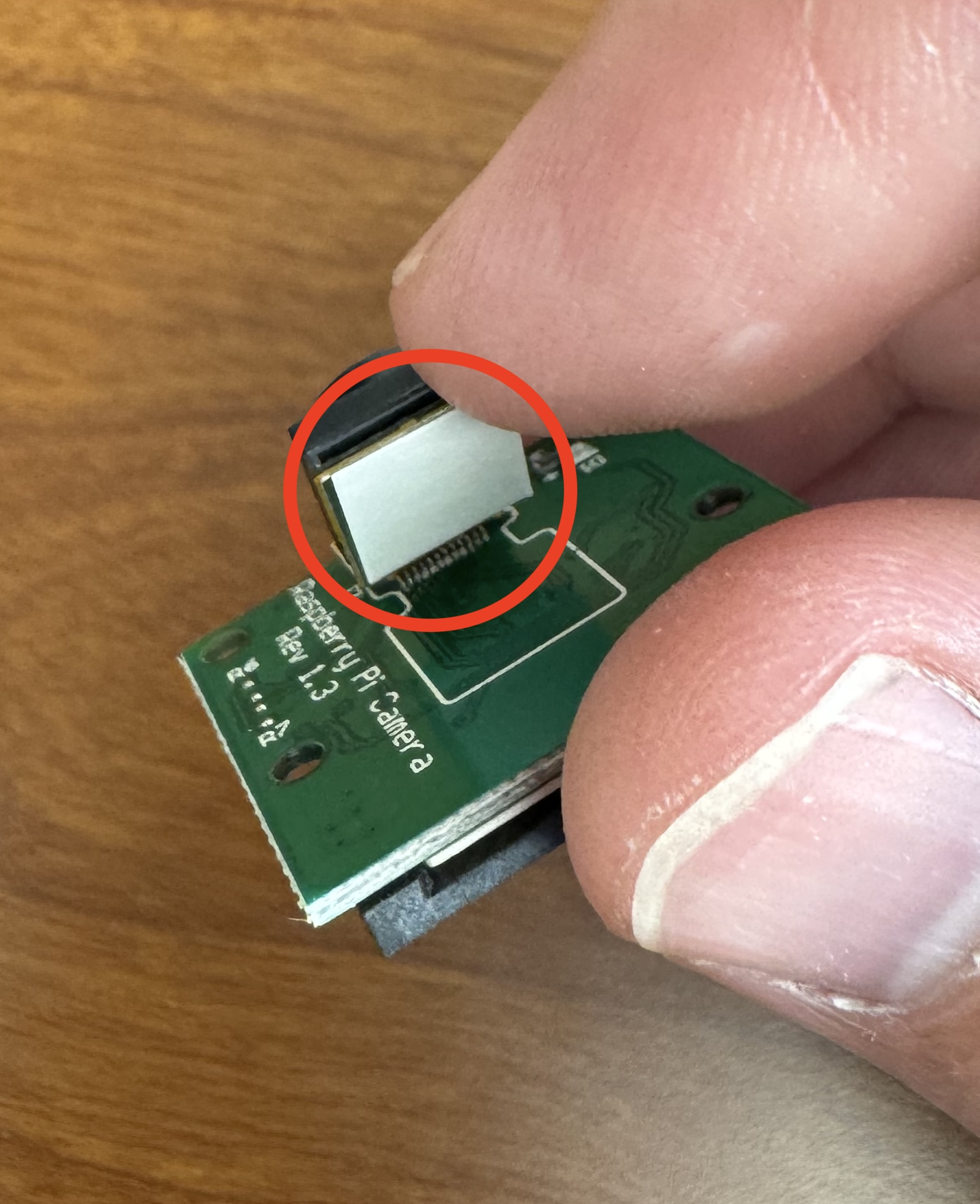
Familiarize yourself with the connector on your camera PCB. Notice the small dark grey shroud around the white plastic of the connector. This shroud “locks” the connector, preventing the cable from being removed. Unlock it by gently pulling on the edges of the shroud until it slides out. Again, use caution.
-
Insert the narrow end of the brown ribbon cable into the Pi’s connector. Copper contacts should face downwards toward the circuit board.
-
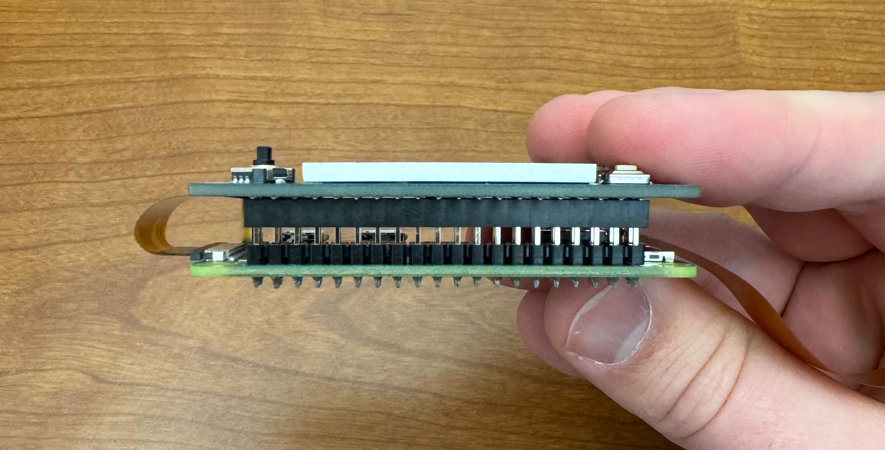
Route the ribbon cable between the Pi and the display HAT. Avoid bending the metal part of the ribbon near the connector.
-
Insert the wide end of the cable into the camera module. Copper contacts should face downwards towards the circuit board. Lock the connector after insertion.
-
Some of the camera modules might not be attached to the green board. If yours is already attached, you can skip this step. If it is not, there is a small adhesive strip on the back of the camera lens. Remove the protective layer and stick it to the camera’s PCB.
-
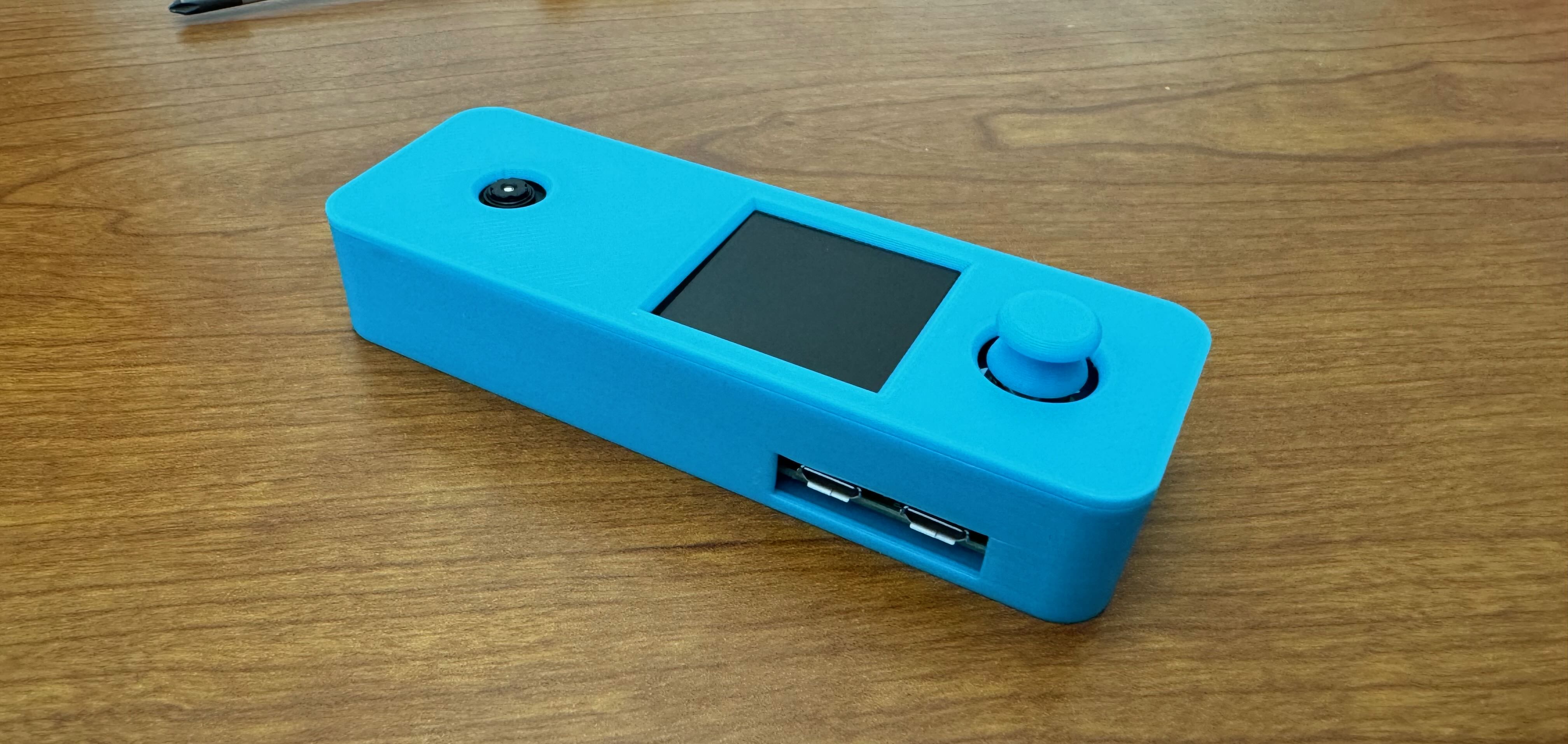
In this lab, you were also given a 3D printed enclosure for your Pi Z2W kit.
Doorbell case 3D printed file. You will need to attach the camera module to the standoffs on the lid. Note that the button in this file is not included in the case you will receive in this lab. As visible in the 3D model above, there are several components that comprise this enclosure. The top of the case is the long, rectangular part with holes for the camera, LCD screen, and button respectively.
Notice: Your kit does not contain a button, as the buttons in this model did not function well enough to be produced.
-
Remove the lens film from the camera. Mount the camera board to the lid of the case using the 4 screws provided.
-
Insert the Pi into the case by aligning the remaining two holes with the case pegs.
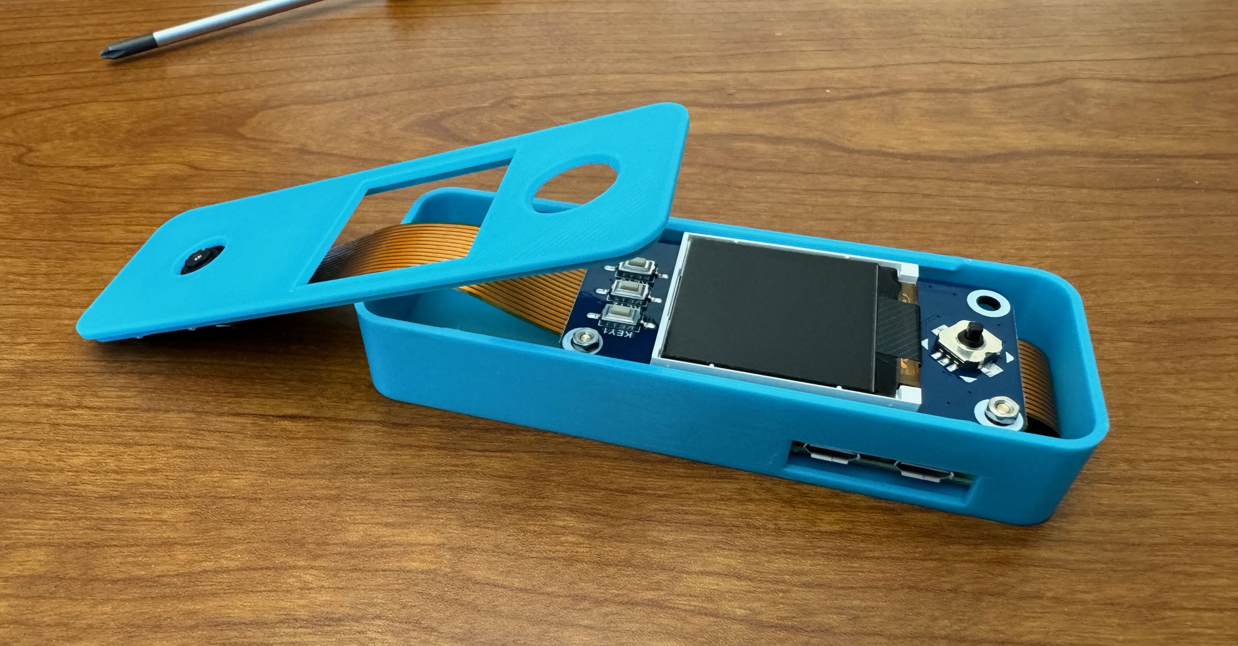
-
Tuck the slack of the ribbon cable under the camera. Be careful not to pinch or crease the ribbon cable.
-
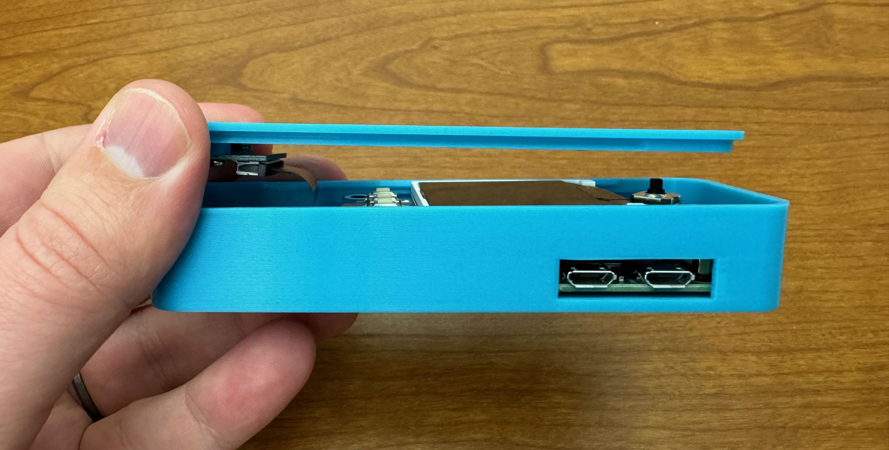
Snap the lid onto the bottom of the case.
Details about the display and camera hardware will be presented in future labs.
Turn your Pi Z2W back on by unplugging the ethernet from the PoE adapter, plugging your PoE adapter into the Pi, and reconnecting the ethernet. Re-connect to the Pi over SSH in VS Code like we did earlier.
Lab Submission
- Demonstrate to a TA that your Z2W is set up correctly. Show them that:
- you can connect to your pi over SSH on VSCode
- your Z2W uses
zsh(the shell installed with the second install script).
- Complete the Learning Suite Pass-off quiz.
- Take a look at the
submission.mdfile included in your Starter-Labs repo. You will fill this out over the next 4 labs.