Table of Contents
Objectives
You are to write an implementation of an FPGA router, and work to optimize the quality of result, runtime, and/or memory usage.
Preliminary
Github Repo
Code and submission is done using Github Classroom. Use this invitation link to create a private Github repository that you will use for the class.
After you create your repository, import the starter code from https://github.com/byu-cpe/ecen629_student using these steps, replacing the repository URL in line 3 with your repo URL (please follow these steps and don’t use the “Import Code” button:
    git clone --bare git@github.com:byu-cpe/ecen629_student.git
    cd ecen629_student.git/
    git push --mirror git@github.com:byu-ecen629-classroom/427-labs-jgoeders.git
    cd ..
    rm -rf ecen427_student.git
System Packages
You will need these system packages:
sudo apt install libx11-dev
Code
The starter code sets up the structures for the FPGA architecture, the routing resource graph, as well as drawing the FPGA and routing. You will only need to implement the actual router code.
FPGA Architecture
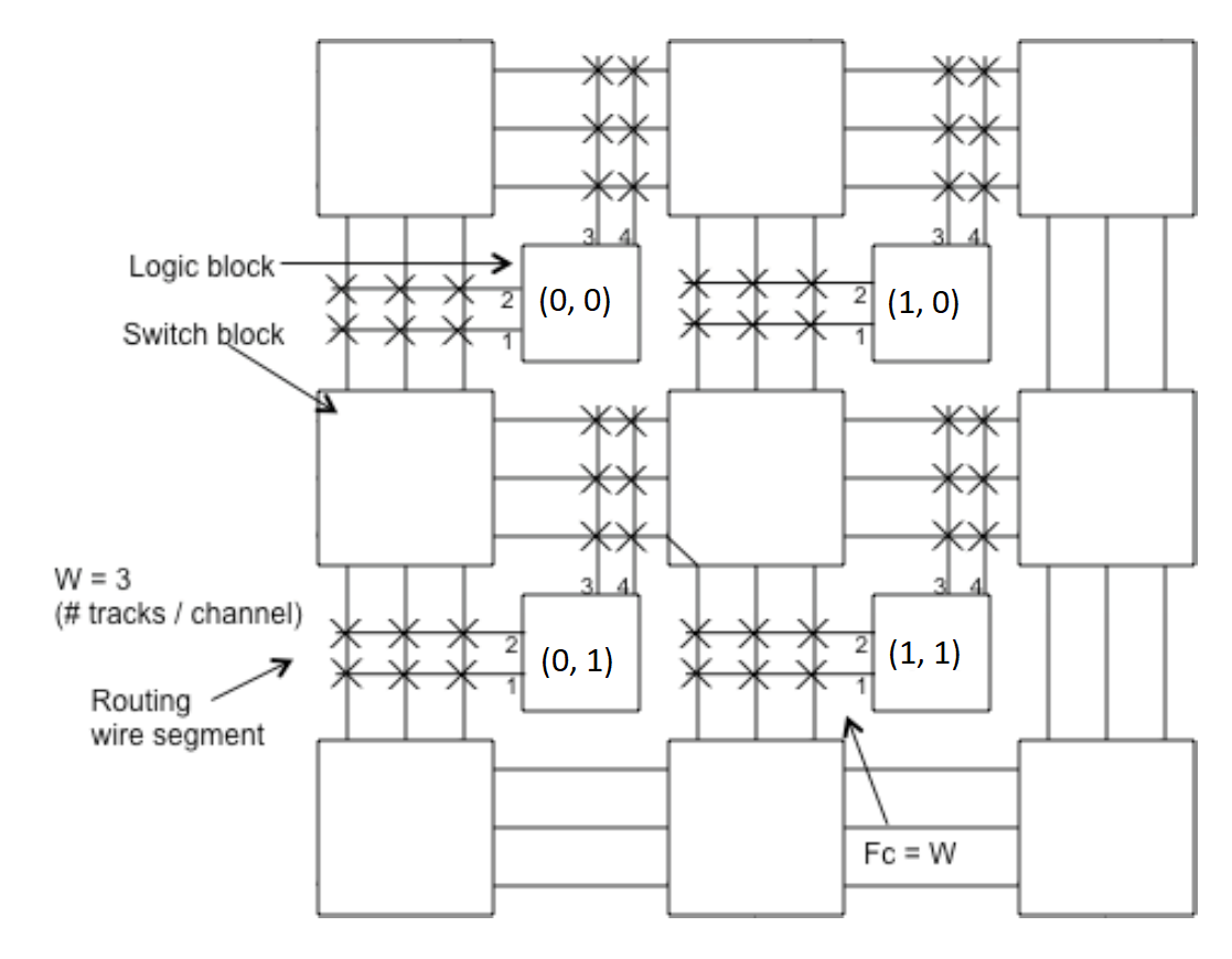
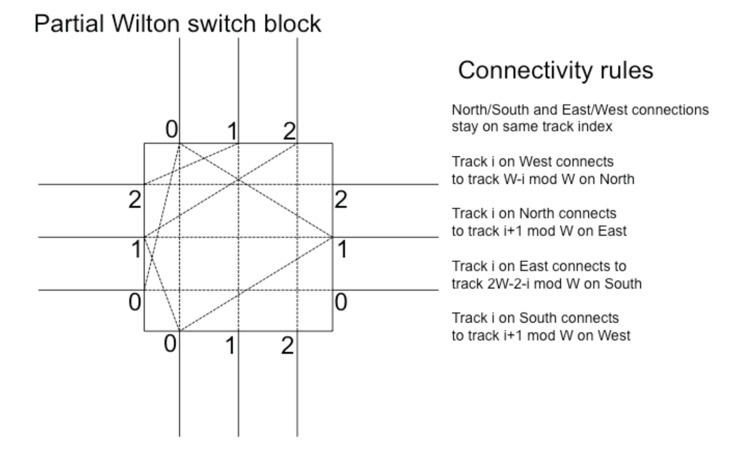
The FPGA architecture is illustrated in the figure below. In the first part of this assignment, each pin can connect to all tracks in the neighboring channel (Fc = W, as shown in the figure). Each routing segment endpoint can connect to three other segments (Fs = 3). The routing segments span one logic block tile. Switches are bidirectional. Switch blocks use the Wilton topology.
Code Structure
- asst_routing.cpp: The main executable. This takes two command-line arguments, the path to the circuit file, and the FPGA channel width.
- Design.cpp/.h: A class containing all nets in the design.
- Drawer.cpp/.h: A class responsible for drawing the FPGA and routing.
- FPGA.cpp/.h: A class that contains a list of all FPGA tiles, as well as the FPGA size and channel width.
- FpgaTile.cpp/.h: A class representing an FPGA tile, containing pointers to neighboring tiles, as well as pointers to the RRNode pins and wires in the tile.
- Net.cpp/.h: A class representing a single net in the design, containing one source RRNode and a list of sink RRNodes.
- Router.cpp/.h: An empty class to implement your router.
- RRNode.cpp/.h: A class representing a single routing resource node (wire segment or pin), with pointers to all connected RRNodes. To assign a Net to be routing using an RRNode, you can call
RRNode->setNet(). When this is called, the net will be drawn appropriately. - RouterSimple.cpp/.h: An example router that calls a maze router for every net, drawing after each net is routed.
- circuits/: Contains a folder of test circuits.
Input Circuit File
The provided program takes as input from a file the following format:
- The first line consists of one integer, n, where n gives the n x n dimensions of the chip in logic blocks. The grid cells are numbered from 0 to n-1 in each dimension.
- The next set of lines has the form
XS YS PS XD1 YD1 PD1 XD2 YD2 PD2 .... Each of these lines gives a net in the design, with source located at (x=XS,y=YS,pin=PS), followed by a list of destinations sinks (x=XD1, y=YD1, pin=PD1), (x=XD2, y=YD2, pin=PD2), etc. This list is terminated by the line:-1 -1 -1 -1 -1 -1.
Example input file:
10                  (10 x 10) grid
1 2 4 2 3 2         Pin 4 on block at (1,2) connects to pin 2 at (2,3)
0 0 4 1 2 3         Pin 4 on block at (0,0) connects to pin 3 at (1,2)
-1 -1 -1 -1 -1 -1   (end of pin pair list)
Building and Running the Router
Build the router using CMake. To run the router, you need to provide a circuit file and channel width:
cd router/build
cmake ..
make
./src/router ../circuits/tiny 12
Graphics Package
The graphics package, EasyGL, is available courtesy of Professor Vaughn Betz, University of Toronto.
The provided code contains a Drawer class, which wraps around easygl:
- To draw the current state of the routing, put
Drawer::draw();in your code. - To display the graphics window and wait for the user to hit the Proceed button, call
Drawer::loop();
By default the code will display graphics only when provided the -d flag, and will display the graphics after routing is complete. If you want to draw the routing after each net is routed, you will want to call both of the above functions, as shown in RouterSimple.cpp.
Implementation
Implement a router that produces a valid routing of all nets in the design. Your router may share wiring among the loads driven by a source pin.
For debugging purposes, you may find it helpful to write your program so that it can display the progress of your algorithm as it routes each step for each connection; that is, you may wish to display each step of the router expansion (though this is not mandatory for this assignment).
You should test your program on the test files provided in the assignment repository. You should determine the minimum channel width (W) for which your router will successfully find a solution. You should then relax the channel width (W+30%) and report results for this as well.
Running Multiple Designs
A script is provided to you, scripts/run_designs.py, that will help you collect results on several designs.
- First run the script with the
--find_min_wargument, to perform a binary search and find the minimum channel width that is routable for each circuit, and write the results to the resuts/minw.csv file. - Next, run the script without the argument to read in your minimium channel width file and run each design with (W=Wmin) and (W=Wmin+30%), collecting segment, runtime and memory results. Results are written to results/results.csv.
Results
-
You should collect the following results:
Circuit W # Routing Segments Runtime Memory Usage small_dense Wmin small_dense Wmin+30% med_dense Wmin med_dense Wmin+30% large_dense Wmin large_dense Wmin+30% xl Wmin xl Wmin+30% huge Wmin huge Wmin+30% Runtime and memory usage can be obtained in Ubuntu by running your command using
/usr/bin/time -v <command>. Memory is available as Maximum resident set size. -
Innovate to improve the performance of your router, and document the effectiveness of your improvements.
What to hand in
- Commit your final updates to your Github Classroom repo before the deadline.
- Commit a PDF report (two page max, min 10 pt) to your repo, containing the following:
- Your final results in a table as shown above.
- A screenshot of the routing of a design of your choice.
- A description of steps you took to improve any of the reported metrics. Where helpful, include charts, figures or code snippets to explain what you chained and how impactful the optimizations were.
Acknowledgement
This assignment was created by Professor Jason Anderson from the University of Toronto. I modified it for our class.