Previous: Installing Vitis/Vivado
Setup
Installing Boards
If you are using a Digilent board, such as the PYNQ Z-2, you need to setup the board files in Vivado. See https://github.com/Xilinx/XilinxBoardStore. For example, to install the files for the PYNQ-Z2 board, you would run:
xhub::refresh_catalog [xhub::get_xstores xilinx_board_store]
xhub::install [xhub::get_xitems *pynq*]
Running Vivado
/tools/Xilinx/Vivado/2024.2/bin/vivado
After launching Vivado, open the Tcl console and run the following to make sure you can access the installed boards from the last step:
set_param board.repoPaths [get_property LOCAL_ROOT_DIR [xhub::get_xstores xilinx_board_store]]
Creating a Simple Hardware Project
Creating the Project
After launching Vivado, follow these steps to create a hardware project:
- Create Project…, and choose a project name and location. You can name your project whatever you want, but make sure you place the project in it’s own directory. For example, my project was named 625_lab5 and located at lab_vitis/hw/625_lab5. (Note that I chose to add a hw subdirectory and then created a project directory within this. You will see why this is useful when you get to the section on Committing to Git). Click Next. Choose an RTL project. Click Next.
- You don’t need to add any sources or constraints yet, just click Next.
- On the next you will be asked to choose an FPGA part. Click Boards at the top, and choose your board (ie. Tul PYNQ). Click Finish to create your project.
Creating a Base Design
In these steps we will create a basic system, containing only the Zynq processing system (PS).
- Click Create Block Design, and click OK on the popup.
- Add the ZYNQ7 Processing System IP to the design (right-click, Add IP).
- A green banner should appear with a link to Run Block Automation. Run this. This will configure the ZYNQ for your board, including configuring the DDR memory controller.
- Add a Processor System Reset IP to the design.
- Add a AXI Timer IP to the design.
- Add a AXI SmartConnect IP to the design.
- Manually connect up the blocks like shown, or use the Connection Automation tool to connect them.
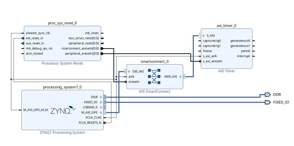
- Open the Address Editor and assign addresses to the AXI Timer (right-click, Assign Address).
- Go back to the Diagram view and Validate Design.
- Generate a top-level module: In the Sources window, expand Design Sources and right-click on your block design (design_1.bd) and select Create HDL Wrapper. Use the option to Let Vivado manager wrapper and auto-update.
Committing to Git
Want to commit your project to Git? Don’t try and commit your actual project files, as this won’t work. Instead, we will instruct Vivado to create a single Tcl script that can be used to re-create our project from scratch:
- Select File->Project->Write Tcl.
- Make sure to check the box Recreate Block Designs using Tcl.
- Those choose a file location. This should be outside your project directory, since your project directory is temporary and not committed to Git. My script is located at
lab_vitis/hw/create_hw_proj.tcl. Commit this Tcl script to Git. - Now, feel free to delete your Vivado project folder, and then you can simply recreate it using
vivado -source create_hw_proj.tcl. I typically create a simple Makefile such as this:
proj:
	vivado -source create_hw_proj.tcl

clean:
	rm -rf 625_lab5
Synthesizing the hardware
- Run Generate Bitstream.
- Run File->Export->Export Bitstream File and save the bitstream (.bit file) to your
lab_vitis/hwdirectory. - Run File->Export->Export Hardware and save the hardware description (.xsa file) to your
lab_vitis/hwdirectory. This file will be provided to the software tools in the next section to tell the software tools all about our hardware system configuration. - Commit these files to Git.
Important: Any time you change the hardware design (eg. changing your HLS IP) or block diagram. You need to recompile the bitstream in Vivado, and re-export the bitstream and xsa file. In addition, if you update your HLS designs, you will need to Refresh the IP in Vivado, before recompiling the bitstream. Vivado keeps a cache of the IP, and if you don’t refresh it, it will use the old IP.