Table of Contents
Learning Outcomes
The goals of this assignment are to:
- Gain experience using a commercial HLS tool, Xilinx’s Vitis HLS tool.
- Observe how changes to the source code affect the resulting resource usage and performance.
- Explore HLS design optimization techniques, and the effect on resource usage and performance.
- Learn about a simple machine learning algorithm.
Background
Handwriting recognition refers to the computer’s ability to intelligently interpret handwritten inputs and is broadly applied in document processing, signature verification, and bank check clearing. An important step in handwriting recognition is classification, which classifies data into one of a fixed number of classes. In this lab, you will design and implement a handwritten digit recognition system based on the k-nearest-neighbors (k-NN) classifier algorithm [wiki, good youtube video].
In the assignment you are provided with a set of already classified handwritten digits (called the training sets), and will implement a k-NN algorithm in C++ that is able to identify any input handwritten digit (called the testing instance) using the training sets. In addition, you will use two commonly-used high-level synthesis (HLS) optimizations to parallelize the synthesized hardware and explore design trade-offs in performance and area.
Getting Started
Code Organization
You are provided the following files:
-
digitrec.cpp: an incomplete source file where you write your k-NN based digit recognition algorithm in C++. -
digitrec.h: the header file that defines the interface for the core functionsupdate_knnandknn_vote. -
typedefs.h: the header file that defines the key data types used in the design. -
training_data.h: the header file that contains all the training data. -
test_data.h: a set of test data with golden values for testing your prediction accuracy. -
digitrec_test.cpp: a test bench (only useful for simulation) that helps verify your code and perform experiments with various handwritten input digits. -
hls_config.cfg.in: a configuration file that contains settings for the Vitis HLS compilation. There are some options in the file that disable optimizations, that you can remove and/or replace later in the assignment. You may want to add your own options as well. The file is named with a.inextension as it is a template file that has a parameterizedKvalue that will be filled in by the Makefile before being used by Vitis HLS. -
Makefile: a makefile for you to easily run:- C simulation:
make c_simulation - C synthesis:
make c_synthesis - You can also override the value of
K_CONSTin your code here, by providingK=?to the make command. Example:make c_simulation K=2ormake c_synthesis K=5.
- C simulation:
-
scripts/collect_results.py: This Python script will run both C simulation and C synthesis to collect accuracy, Fmax and resource usage forKvalues 1-5. It will output a csv file with the results in theresultsfolder.
Setting up Vitis HLS
For this assignment we will be using Vitis HLS. You can install Vitis on your local machine (https://www.xilinx.com/support/download.html). If you do this, you should install Vitis 2024.2. If you run into problems launching the GUI, you can try this fix.
Note: If you prefer, you can install Vitis on a Windows machine. I haven’t tested this. It should work with the assignment, with a few extra considerations. For example, the Makefile which has been provided to quickly compile and run your design may not work unless you have a build system setup. You can still build and run within Vitis HLS, so it is not a big difference, but keep in mind you may run into problems such as this.
Before running the Vitis tools you should do the following:
source /tools/Xilinx/Vitis/2024.2/settings64.sh
Vitis GUI vs command line
For this assignment you can use the Vitis GUI, or you can work entirely via command line. The GUI provides the advantage of being able to view the schedule, violations, and other information in graphical form. You will need a free Vitis HLS license in order to use certain features in the GUI. If you are using CCL1, there is a license file available at /data/625_hls/Xilinx.lic. Copy it to your ~/.Xilinx/ directory:
cp /data/625_hls/Xilinx.lic ~/.Xilinx/
Design Overview
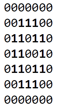
You are given 10 training sets, each of which contains 1800 49-bit training instances for a different digit (0-9). Each hexadecimal string in training_set_# represents a 49-bit training instance for digit #. The 49 bits of each instance encodes a 7x7 matrix of binary values (i.e., a bitmap). For example, e3664d8e0016 in training_set_0 is a training instance for digit 0 and translates into the following binary 2D matrix and bitmap:

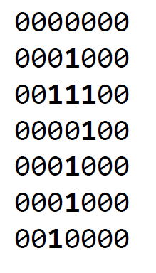
41c082041016 in training set 7 is a training instance for digit 7 and translates into the binary 2D matrix and bitmap shown below:

As you can see, the resolution of the digit is limited by the number of bits (49 bits in our assignment) used to represent it. Typically, increasing the number of bits per instance would improve the resolution and possibly the accuracy of recognition.
We would like to devise an algorithm that takes in a binary string representing a handwritten digit (i.e. the testing instance) and classify it to a particular digit (0-9) by first identifying k training instances that are closest to the testing instance (i.e., the nearest neighbors), and then determining the result based on the most common digit represented by these nearest neighbors.
You are encouraged to read through the links provided above to familiarize yourself with the basic concepts of the k-NN algorithm. In this assignment, we define the distance between two instances as the number of corresponding bits that are different in the two binary strings. For example, 10112 and 01112 differ in the two most significant bits and therefore have a distance of 2. 10112 and 10102 differ only in the least significant bit and have a distance of 1. As a result, 10112 is closer to 10102 than to 01112.
Implementation
Coding and Debugging
Your first task is to complete the digit recognition algorithm based on the code skeleton provided in digitrec.cpp. In particular, you are expected to fill in the code for the following functions:
-
update_knn: Given the testing instance and a (new) training instance, this function maintains/updates an array of k minimum distances per training set. -
knn_vote: Among 10·k minimum distance values, this function finds the k nearest neighbors and determines the final output based on the most common digit represented by these nearest neighbors.
Note that the skeleton code takes advantage of arbitrary precision integer type ap_uint. A useful reference of arbitrary precision integer data types can be found in the user guide.
How you choose to implement the algorithm may affect the resulting accuracy of your design as reported by the test bench. We expect that your design would achieve an accuracy of at least 89% on the provided testing set. You may use the console output or the generated out.dat file to debug your code.
Design Exploration
The second part of the assignment is to explore the impact of the k value on your digit recognition design. Specifically, you are expected to experiment with the k values ranging from 1 through 5, and collect the performance and area numbers of the synthesized design for each specific k. A script is provided to do this automatically.
Design Optimization
The third part of the assignment is to optimize the design with HLS pragmas or directives. In particular, we will focus on exploring the effect of the following optimizations in our design and apply them appropriately to minimize the latency of the synthesized design.
- loop pipelining: Allows for overlapped execution of loop iterations by leveraging pipelining techniques.
- loop unrolling: unfolds a loop by creating multiple copies of its loop body and reducing its trip count accordingly. This technique is often used to achieve shorter latency when loop iterations can be executed in parallel.
- array partitioning: partitions an array into smaller arrays, which may result in an RTL with multiple small memories or multiple registers instead of one large memory. This effectively increases the amount of read and write ports for the storage.
Please refer to the user guide for details on how to apply these optimizations. You may insert pragmas or modify the configuration file to apply optimizations.
You are encouraged to experiment with these optimizations, and others (eg. code restructuring), to achieve the best solution possible. You are welcome to remove the lines in the configuration file that disable optimizations. For this part of the assignment, you only need to set k to 3.
Your proposed solution must meet the clock period constraint, and must not exceed the resources available on the targeted FPGA (xc7z020clg484-1).
For the sake of simplicity, please try to only use fixed-bound for loop(s) in your program. Note that data-dependent for and while loops are synthesizable but may lead to a variable-latency design that would complicate your reporting (You would need to perform C-RTL co-simulation to get the actual cycle count for a design with data-dependent loop bounds).
Class Results
On Teams I will post a link to a spreadsheet where you should post the results of your best solution. There will be two categories for rankings:
- Minimum Latency: Minimum latency provided the design fits within the resources constraints of the chip, and achieves 89% accuracy.
- Most resource efficient: The goal in this category is to minimize the expression r2 · L, where r is the resource usage and L is the total latency. The resource usage will be defined as the maximum fraction of resource usage for any given resource type (BRAM, DSP, FF, LUT).
Report
Include a short report located as lab_vitis_hls/report.pdf with the following:
- Describe how you implemented the update_knn and knn_vote functions.
- Compare different k values with a table that summarizes the key statistics including the error rate (accuracy), area in terms of resource utilization (number of BRAMs, DSP48s, LUTs, and FFs), and and performance in latency in number of clock cycles. Use may want to use the csv file generated by the script.
- Describe how you added HLS pragmas/directives to minimize the latency of the synthesized design. Please contrast the performance and area of your most optimized design (i.e., with smallest latency) with the baseline design. For this comparison, you only need to set k to 3.
- Use charts, snippets of code, or any other presentation techniques to communicate your design decisions and results.
Submission
Submit your code using tag lab4_submission.
Acknowledgement
This assignment was originally written by Professor Zhiru Zhang from Cornell University. I have modified it slightly for our class. The design was originally created by Professor Zhang’s students, Ackerley Tng and Edgar Munoz.