Previous: Vitis Tutorial
This page discusses how you can export your IP from Vitis HLS to be used in a Vivado project, and ultimately to communicate with the HLS accelerator from a Vitis software proj ect.
Package your HLS IP
Leave your HLS files from the last lab in the lab_vitis_hls folder. There are new directories to use in lab_vitis/hls for this lab.
First, go to lab_vitis/hls/digitrec_local, and paste your digitrec.cpp solution from the last lab. You can use an optimized or unoptimized version, just be aware that if your solution uses a lot of resources, it may not fit in the FPGA with the other components we will add, or may not compile, meet timing, etc.
This directory will be used for a solution where the traning memory is stored locally on the FPGA. In a later part of the lab, you will create another variant where the training data is stored in main memory.
- Run
make c_simulationto verify that your code still works. You will need to rename your digitrec function to digitrec_local. - Since our goal is to communicate with the HLS IP from software, we will add a Slave AXI connection to our HLS IP core so that it can be connected to the ARM AXI bus.
- Use the #pragma HLS INTERFACE directive to indicate that the function control should be an AXI4-Lite slave interface (port=return is used for the block-level interface protocol)
- Use the #pragma HLS INTERFACE directive to indicate that the input data should also be an AXI4-Lite slave interface. Make sure these are bundled together (this is the default if you don’t specify separate bundles).
- Run
make c_synthesis. Inspect the report and make sure it is reporting an AXI4-Lite interface. - Run
make packageto create a Vivado IP package. This package will be placed in temp/hls/impl/ip. You can look at the drivers that are created in the drivers subdirectory.
Modifying Your Hardware
Add you IP to your Vivado project:
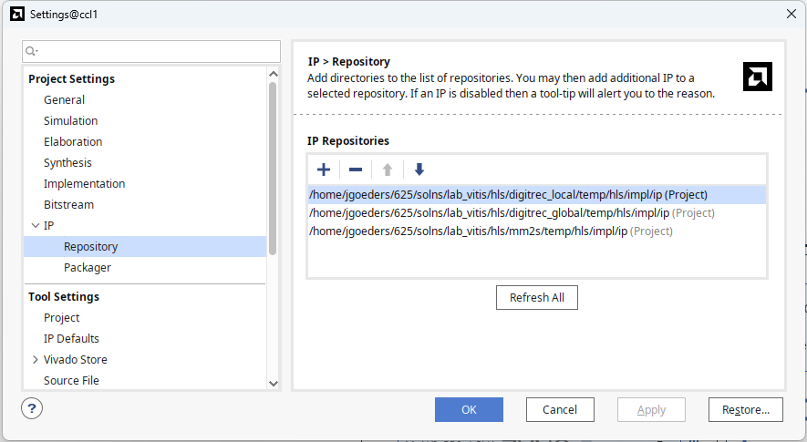
- Click Project Manager->Settings and in the pop-up window, go to IP->Repository, Add the path to your ip directory.
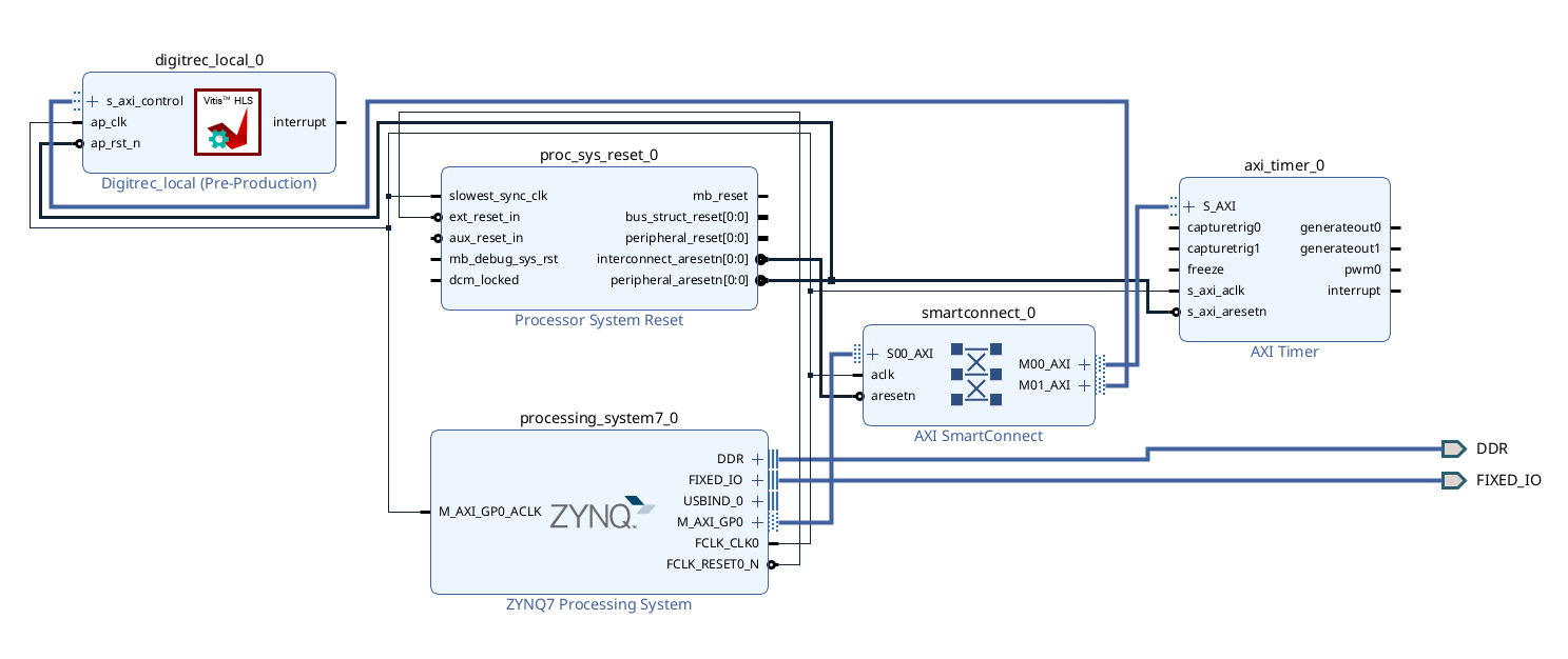
- Go to your block diagram, and add your digitrec_local IP. If you completed the last step correctly, you should see your IP with an AXI4-Lite interface.
- Connect up your IP, or use the Run Connection Automation tool to connect it to the ARM processor. Assign a base address to your IP.
- Generate a new bitstream and XSA file.
Communicating with your HLS IP from Software
Updating Your Platform Component
- Launch Vitis update your Platform Component. Go back to the /ecen625/vitis-tutorial/ page for instructions on updating the platform component with your new XSA file.
- Compile your platform component.
Creating a Software Application
- Update your application software. You can use the main.cpp provided.
- You will see that this code includes xdigitrec_local.h. Take a look at this file, along with xdigitrec_local_hw.h. Inspect the source code and locate:
-
xdigitrec_local_hw.h has register offsets for your IP core. If you followed the steps correctly, you should have:
- control register
- interrupt registers
- return value register
- function argument register, and more.
- xdigitrec.h provides a higher-level driver interface, with functions for starting your accelerator, checking if it’s done, setting argument inputs, etc.
-
xdigitrec_local_hw.h has register offsets for your IP core. If you followed the steps correctly, you should have:
- Look over the timer code in main.cpp. This code will measure the time it takes to run your accelerator.
- Build your application and run it on the board. The runtime should be very similar to the predicted latency from your HLS report. Make note of the runtime, as you will need to provide it in your report.