Table of Contents
The goal of this experiment is to carry out a bus snooping attack at board level which leads to retrieving secret information from a system through physical access.
Preliminary
The name bus sniffing or bus snooping comes from a technique used in distributed shared memory systems and multiprocessors to achieve cache coherence. You can read more about it here.
Bus snooping can also be used as a security attack vector to extract sensitive information from a system by monitoring the data being transmitted over the bus. This can be done on various buses, including those on printed circuit board (PCB) level. The goal is to extract secret information (such as encryption key, firmware, sensed data) from a PCB through physical access.
Bus snooping attack can be implemented without any help of the software portion of the system. It involves eavesdropping or even altering of data that are transferred between the two or more components of a system. Usually, in a PCB, there are numerous traces and other wires and ports that are passing signal which can be secret data or commands which are crucial to the system operation. Snooping the traces by soldering additional components or wires allows the attacker to leak those sensitive data. The system can be forced to shut down or do something malicious just by altering the critical signals. In fact, this is how the original Microsoft Xbox was initially hacked. The link between the Southbridge and EEPROM on the Xbox was observed during boot up and modified to allow the hackers access to the protected region of the Xbox’s hard drive. In mobile devices, the successful snooping attack may allow the attacker to interfere with data between SoC and DRAM or SoC and NAND Flash. Furthermore, the adversary can capture and alter code and data which is written from SoC to memory. One of those tools was a USB cable with embedded hardware called Cottonmouth-I—a cable that can turn the computer’s USB connections into a remote wiretap or even a remote control.
Instructions
Part 1: Setup
The figure below shows the bus connection that you will be snooping.
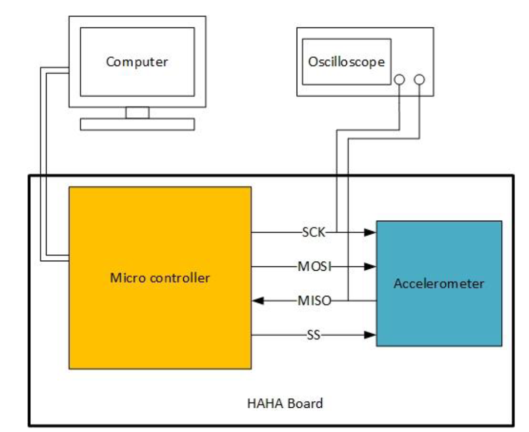
-
You are provided two hex files for this lab, although you should only need one of them. If the accelerometer was working from the Self-Test, program the microcontroller with
U_1.hex, otherwise programU_2.hex. The former will send accelerometer data over the bus, while the later will send some pre-defined data that does not use the accelerometer.NOTE: You may need to tap MCU RST button multiple times before the LEDs show the correct value and change as you move the board.
- Turn OFF the HaHa Board.
- Clip the oscilloscope probes to the
MISOandSCKpins of the SPI header (P2) on the HaHa Board. Connect both ground clips to the screws labeledGND. (Refer to the HaHa User Manual to find the right signal). - Turn ON the HaHa Board.
- Observe the pattern of traffic on the two lines. If using the accelerometer data your, tilt the PCB around and see how the traffic changes as well.
Part 2: Measurement, Calculations, and Questions
Answer the following questions in your REPORT:
- Take a photo of your experiment setup, showing the oscilloscope probes connected to the HaHa board.
- Which hex file did you use to run this experiment?
- Which line is the clock line? What is the clock period? What frequency does this correspond to?
- Which line is the data line? Can you determine the data being sent?
- Take at least two pictures of the data being sent.
- Try and decode this into hex values.
- For U_1.hex, if you tilt the PCB in one direction (try different angles) how does the data packet change? How does it stay the same?
- For U_2.hex: what is the pattern in the data? Does it ever remain the same? Why would a pattern like this show up on the bus?
- If you didn’t have conveniently labeled traces to probe, how you would figure out which traces would you probe if you needed to figure out how the board worked?
- How would you prevent such attacks? If the data transmitted over this bus was critically important and could not be intercepted, how would you secure the communications? How would you then debug any issues that arose because of your fix?
What to Submit
Create a lab report document that contains the items mentioned above. Make sure to save this as lab_bus_snooping/report.pdf,
and submit as tag lab_bus_snooping, using the submission instructions.
Acknowledgement
These instructions were originally from Dr. Swarup Bhunia, University of Florida, and were modified for this class.