This tutorial will guide you through the process of reviewing, simulating, synthesizing, and implementing a simple SystemVerilog design on the Basys3 FPGA development board. This example includes SystemVerilog files that define a simple counter circuit that counts the number of times a button has been pressed on the Basys3 board. There are several questions embedded in this tutorial that you should answer in your laboratory report.
Overview of the buttoncount Design
The buttoncount design involves three SystemVerilog files: buttoncount.sv located in buttoncount tutorial directory; oneshot.sv and synchronizer.sv (both in the include directory).
The buttoncount.sv file contains the top-level button counter logic.
The oneshot.sv file contains the logic for implementing a simple one-shot pulse detector and synchronizer.sv contains the logic for a two-flip-flop synchronizer.
Review the text of these SystemVerilog files to familiarize yourself with the SystemVerilog syntax and the coding style.
The top-level buttoncount.sv file contains a counter to keep track of the number of button presses
The synchronizer.sv file contains a simple two-flip-flop synchronizer that is used to synchronize the button press signal to the global clock signal.
The file oneshot.sv contains the state machine that is used to make sure that the counter is incremented only once each time the button is pressed.
A summary of these components is described below:
buttoncount.sv
The code in this top-level design includes a 16-bit counter that will increment every time the button is pressed. It also includes a synchronizer to synchronize the button signal to the global clock signal. The counter is reset with a synchronous reset signal (the center button). The output of the counter are tied to the LEDs on the Basys3 board.
What line of code in this file describes the logic used to assign the count value to ‘zero’ when the ‘rst’ signal is asserted?
oneshot.sv
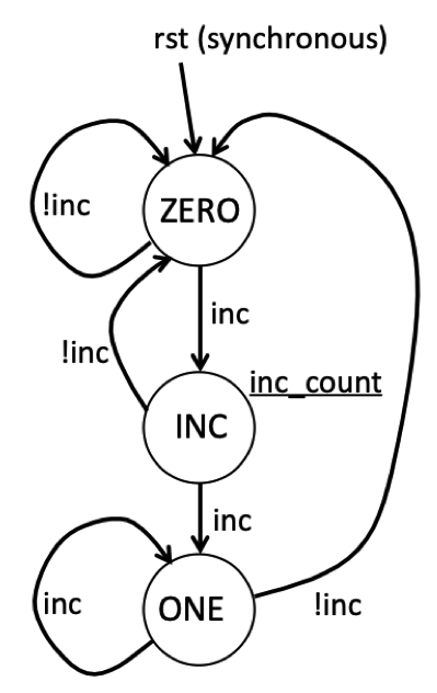
This file includes a state machine that is used to detect the first clock cycle in which the up button transitions from ‘0’ to ‘1’. The reason this state machine is needed because we do not want to increment the counter for every clock cycle in which the button is pressed. If we did this, the counter would increment too fast for us to see any impact. This state machine keeps track of what the history of the button press has been and then generates an output signal, ‘inc_counter’, that is asserted for only one clock cycle when the button is first pressed. This is sometimes called a “one shot” detector because we want only one clock cycle signal for a long button press.
The state diagram for this state machine is shown below. This state machine has three states: ZERO, INC, and ONE. In the ZERO state, the state machine is waiting for the input signal ‘inc’ to go high. As long as ‘inc’ remains low, the state machine remains in this state. When the input ‘inc’ goes high, the state machine will move to the INC state. During the INC state, the Moore output signal ‘transition’ is high indicating that the input has made a transition from 0 to 1. The state machine will transition from the INC state back to the ZERO state if the ‘in’ signal is zero, otherwise it will move to the ONE state (i.e., when ‘inc’ is 1). The state machine will remain in the ONE state until the ‘inc’ signals returns back to zero. This state machine includes a synchronous reset signal named ‘rst’ that will return the state machine back to the ZERO state on the next positive clock edge.
After reviewing the code for this buttoncount circuit, determine the values of the ‘inc_count’ signal and the counter value by completing the waveform below.
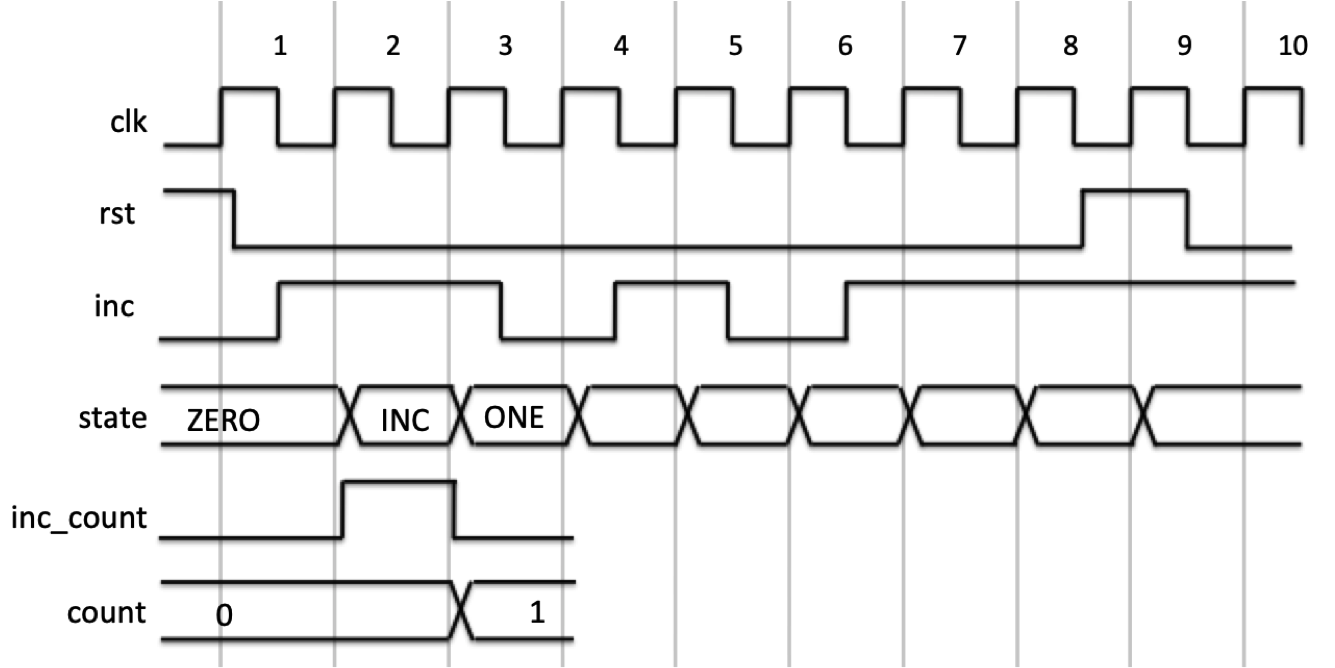
Complete the questions about the waveform in the laboratory report.
Vivado Simulation
In this course, you will use the Xilinx Vivado design software to design digital circuits and then test those designs on the Basys3 FPGA board. This software is installed on computers in the digital lab and embedded lab for this class. Having taken ECEN 320, you should already have an understanding on how to run the Vivado tools. If you are unfamiliar with these tools you may want to review the ECEN 320 Vivado Tools lab. Links to relevant tutorials from this lab will be provided throughout this lab to help you get started.
Begin by configuring your environment to access the Vivado tools and run the Vivado tool by executing the setup script located at /tools/Xilinx/Vivado/2024.1/settings64.sh.
You will need to execute this script every time you run the tools and may want to add this to your shell startup script (e.g., .bashrc or .zshrc).
Indicate the version of Vivado that is installed in the digital lab
Vivado Command Line Execution and Makefiles
For this class you will run the Vivado tools from the command line. Because multiple commands are often needed to perform common functions, you will use makefiles to automate these tasks. Each laboratory assignment will require you to create a makefile that performs a number of specific tasks such as simulating your design, synthesizing your design, and generating a bitstream for your design. If you are rusty on using the Vivado simulator, review the ECEN 320 Simulator tutorial to remind you which commands are used to analyze, elaborate, and simulate your SystemVerilog.
A makefile has been created in the local repository to demonstrate how to execute a variety of Vivado tools from the command line. Several rules have been defined to support the simulation of the buttoncount design. These rules include:
analyze_buttoncount: This rule calls thexvlogcommand to analyze the SystemVerilog files used in the buttoncount design.elab_buttoncount: This rule calls thexelabcommand to elaborate the top-level design.elab_buttoncount_tb: This rule calls thexelabcommand to elaborate the top-level design.sim_buttoncount_gui: This rule calls thexsimcommand to simulate the design in GUI mode.sim_buttoncount_tb: This rule calls thexsimcommand to simulate the design in command line mode with a testbench.
Interactive Vivado Simulation with TCL Simulation Scripts
A common way to simulate your circuits early in the design process is to simulate them interactively with a GUI and TCL simulation scripts. This approach allows you to interactively set inputs, run the simulation, and view the waveforms. Start the interactive simulator for the buttoncount design by executing the following makefile rule from the command line:
make sim_buttoncount_gui
Once the simulator has started, add the internal signals of the buttoncount module to the waveform viewer.
You can do this by selecting all signal names in the ‘Objects’ pane, right clicking and select “Add to Wave Window”.
You can interactively guide the simulation by using force commands to set the input values and the run command to run the simulation for a specific amount of time (see the command line simulation tutorial and the GUI simulation tutorial to learn more about Tcl simulation commands).
A TCL simulation script, buttoncount_sim.tcl, is included in the local repository to simulate an input waveform.
This script contains a number of Tcl commands to set the inputs, drive the clock, and run the simulator.
Once your simulator is running, execute the buttoncount_sim.tcl by executing the following Tcl command in the simulation Tcl command interpreter: source buttoncount_sim.tcl.
After executing this script, you should see the waveform output of the internal signals. Review the waveform output and answer the following questions. In some labs you will be required to take a screenshot of the waveform output and include it in your lab report (it is not required for this tutorial).
Answer the questions in the lab report regarding the results of this simulation waveform output.
Testbench Vivado Simulation
In most of the laboratory assignments in this class you will be provided with a testbench SystemVerilog file to simulate your design and verify its operation.
A file buttoncount_tb.sv has been created to demonstrate how to use a testbench to simulate the buttoncount design.
A makefile rule sim_buttoncount_tb is included in the makefile to simulate the buttoncount design with this testbench.
This testbench generates a log file that can be reviewed for correctness.
Run this testbench simulation by executing the following command:
make sim_buttoncount_tb
After running this simulation, answer the following questions:
What is the value of the LEDs at the end of the simulation?
Vivado Synthesis
In this exercise, you will go through the steps required to implement your buttoncount module and target it for the Basys 3 FPGA board. As you may remember from ECEN 320, there are many steps involved in preparing your SystemVerilog module for the Basys 3 FPGA board. These steps will be summarized below.
.xdc file
Each design you create will need a .xdc file to map the top-level input/output ports to specific pins on the Basys 3 board.
The file buttoncount.xdc has been created for the buttoncount design.
This file uses the following input/output resources on the Basys3 board:
- The global clock input ‘clk’ is connected to the 100 MHz clock
- The ‘rst’ input is connected to the center button (BTNC)
- The counter outputs are connected to the light emitting diodes (LEDs) LD15-LD0 (i.e., count[15], count[14],…,count[0])
Once you have the .xdc file you can proceed to the logic synthesis step. The logic synthesis step will take your SystemVerilog code and synthesize a digital circuit from it. If you are rusty on the synthesis process, review the ECEN 320 Synthesis Tutorial. These instructions will assume you are familiar with the synthesis process.
Synthesis Scripts
The synthesis step requires a synthesis Tcl script to guide the synthesis process.
A synthesis Tcl script named synth_buttoncount.tcl has been created in the local repository to guide the synthesis process for the buttoncount design.
Review the contents of this script to familiarize yourself with the synthesis commands.
A makefile rule named buttoncount_synth.dcp has been created in the makefile to run this synthesis script.
It creates a design checkpoint file (.dcp) that is used later in the implementation process.
It also create a log file named synth_buttoncount.log that contains the synthesis messages.
The messages generated by the synthesis step are very important, and it is essential to review the synthesis logs carefully.
You will be required to create log files for all synthesis steps in this class.
Run the makefile rule to generate the buttoncount_synth.dcp file and review the synthesis log file.
Answer the following questions based on your review of the synthesis log file.
How many “FDRE” primitives were inferred during synthesis of the ButtonCount design?
What type of state machine encoding style was used for the state machine generated by the ‘OneShot’ module?
Implementation and Bitfile Generation
The next step in the process is to implement the synthesized logic onto the FPGA found on the Basys 3 board.
This step starts with the buttoncount_synth.dcp generated by the synthesis step and performs placement and routing of the synthesized design onto the FPGA.
Details on how to perform the implementation step from the command line can be found at the following ECEN 320 Tutorial.
Like the synthesis step, the implementation step requires a Tcl script to guide the implementation process.
A Tcl script named impl_buttoncount.tcl has been created for you as an example implementation script.
A makefile rule named buttoncount.bit is included in the makefile to run this script.
In addition to the bitfile, this makefile rule generates a log file named imp_buttoncount.log that contains the implementation messages as well as two report files: buttoncount_utilization.rpt and buttoncount_timing.rpt.
Run this makefile rule to generate the bitstream and logs.
When you are done, answer the following questions based on your review of the log and report files.
Indicate the number of resources consumed by the ButtonCount design in the laboratory report.
Determine the “Worst Negative Slack” or WNS of the ButtonCount circuit.
Bitstream Download
The last step in the process is to download the generated bitfile onto the Basys 3 board to make sure your circuit is working properly. Review the ECE 320 Download tutorial to refresh your understanding of how to download bitfiles onto the Basys 3 board. Download the bitstream for your buttoncount circuit to a Basys 3 board. Make sure the board operates correctly by pressing BTNU to see the LED count increase. Also, press BTNC to reset to make sure the counter resets.
Intermediate File Cleanup
All the steps completed for the buttoncount example will generate intermediate files.
As described above, these files must be ignored by your GitHub repository by adding entries into the .gitignore file for the lab.
These intermediate files must also be removed when the make clean rule is run.
A makefile rule named ‘clean’ has been added to the makefile.
Lab Passoff
Each of your lab assignments will require you to submit your work for a passoff using the python passoff.py script.
This buttoncount design example also includes a passoff.py script to demonstrate how to use this script to prepare your lab for submission.
The passoff script performs a number of checks to make sure you have completed all the required steps for the lab and that your lab is ready for submission.
- Performs all the makefile rules to make sure they run correctly and generate the correct files
- Checks the output of the files generated by the build process to make sure they are correct
- Performs a ‘make clean’ to clean the repository
- Checks the repository to make sure it has all the included files, there are no uncommitted changes, and there are no intermediate files included in the repository.
- Submits your lab to GitHub for grading using the appropriate GitHub tag.
It can be a hassle to prepare your submission properly to pass all the passoff checks. The passoff script includes a number of options to help you debug and prepare your submission without completing the entire passoff process. The following options are available in the passoff script:
python3 passoff.py --required_files: lists the files required in your repository for the passoff.python3 passoff.py --makefile_rules: summarizes the makefile rules you will need to implement to complete the labpython3 passoff.py --make_rule <rule>: run a single makefile rule from the passoff script to make sure the passoff script is happy with your implementationpython3 passoff.py --build: Runs all makefile rules from the passoff script to make sure everything is working correctly. This option will perform a ‘clean’ before running the build (unless the--nocleanoption is also specified).python3 passoff.py --check_repo: Runs all makefile rules from the passoff script to make sure your repository is ready for submission (i.e., all required files are included, there are no uncommitted changes, and there are no intermediate files included in the repository).python3 passoff.py --submit: Submits your lab to GitHub for grading (after performing all the checks). This will perform multiple steps to make sure that (1) your lab builds properly, (2) your repository is ready for submission, and (3) your lab is submitted to GitHub with the appropriate tag.
Experiment with these options to help you prepare your lab for submission. Make sure you successfully “submit” this buttoncount example using the passoff script using the –submit flag to make sure you understand how to use this script for this lab and all future labs. You do not need to actually create any files for this tutorial submission - the intent of the submission is to make sure you are familiar with the passoff process on a working lab example. You will not be graded on this submission.
Indicate the number of resources consumed by the ButtonCount design in the laboratory report.
Determine the “Worst Negative Slack” or WNS of the ButtonCount circuit.