Table of Contents
Lab 12 - Final Project
For this laboratory you will write a custom program for your RISC-V processor that implements a simple game on the Basys 3 board. In addition, you will create custom modifications to your processor to demonstrate your ability to modify your processor design.
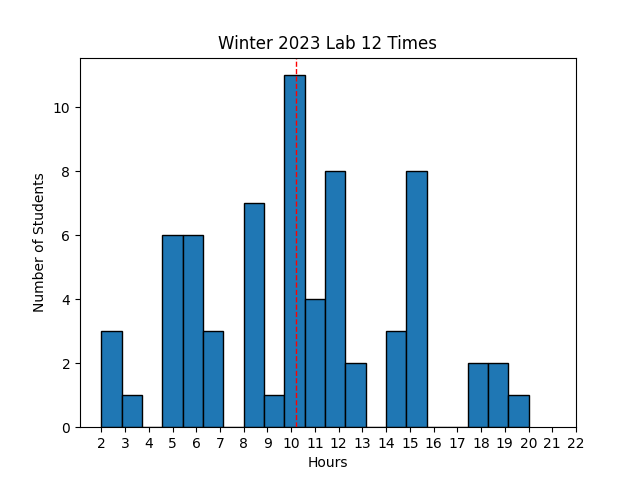 Avg Hours: ? (Winter 2022)
Learning Outcomes
- Demonstrate understanding of RISC-V assembly language programming
- Create custom software that controls the I/O interfaces of the FPGA system
- Extend your processor design to support new instructions and features
Preliminary
In this final laboratory you will be able to create a custom program that executes on your RISC-V processor and that implements some interactive activity such as a game. This preliminary will guide you through a number of steps that you will need to prepare you to complete this custom program. The interactive program you create for this lab should be creative, and you should try to choose something that interests you and ideally entertaining. The following suggestions may help you come up with some ideas:
- A “paint” program that allows you to move the cursor around the screen using the buttons and then place or “paint” the custom character at the cursor location
- A simple Pong game that moves a ‘ball’ across the screen along with controllable paddles to hit the ball back and forth
- Draw a moving snake on the screen that reacts to the user’s buttons
- A simple Tetris game with rotating blocks falling down the screen
- A Hangman game that requests letters from the user and builds a hangman guy as mistakes are made
There are several additional capabilities and features of the I/O subsystem that will help you create a fun and interesting game. The preliminary will review several of these features.
Font ROM
The I/O system circuit provided in previous labs contains an internal memory used to store a “font” of characters available for display.
The contents of this memory are defined in a file found at: ./resources/iosystem/cores/vga/font_mem.sv.
This memory is “Read Only Memory” (ROM) and cannot be changed at run-time.
Each character is defined as an image that is 8 pixels wide and 16 pixels high.
The characters are defined with two colors: foreground and background (i.e., on and off).
The figure below demonstrates the definition of the character ‘A’ in this font using red pixels for the foreground and white pixels for the background:

The description of each character is defined within a text file that indicates which pixels are in the foreground (on) using a binary ‘1’ and which pixels are in the background (off) using the binary ‘0’. The following example demonstrates the text lines in this file that define the character ‘A’:
// code x41
00000000   // 0
00000000   // 1
00010000   // 2    *
00111000   // 3   ***
01101100   // 4  ** **
11000110   // 5 **   **
11000110   // 6 **   **
11111110   // 7 *******
11000110   // 8 **   **
11000110   // 9 **   **
11000110   // a **   **
11000110   // b **   **
00000000   // c
00000000   // d
00000000   // e
00000000   // f
Each line of the text file defines eight bits of one row of a character. There are 16 lines for each character along with comments (i.e., ‘//’) indicating what the character should look like. The characters are ordered by their ASCII value. The entire font is defined in this text file. Browse through this font ROM file and its contents to answer several questions in learning suite.
Determine the character represented by 0x18 in the file
What is the 8-bit binary value associated with line 7 of the 0x35 ASCII character (i.e., the number 5)?
You can modify the font memory to create new characters that are more useful for the game you create in this lab. You can come up with custom non-ASCII characters that are specific for your lab project. For this lab, you will be required to modify the font ROM to include new characters to represent unique figures for your final lab. The example below demonstrates a simple attempt at a Pac-Man character. Note that you can create larger images by using multiple unique characters side by side and above and below each other.

Binary file representation of the pacman character:
// custom character
00000000   // 0
00000000   // 1
00000000   // 2
00000000   // 3
00011000   // 4    **
01111110   // 5  ******
01111100   // 6  *****
11110000   // 7 ****
11110000   // 8 ****
01111100   // 9  *****
01111110   // a  ******
00011000   // b    **
00000000   // c
00000000   // d
00000000   // e
00000000   // f
Character Colors
As the preliminary of Lab #10 described, you have the ability to set a default foreground color and background color for the characters displayed on the screen. In addition to setting a default foreground/background color, it is also possible to set a custom foreground and background color for each character on the display. This allows you to create interesting colored characters with differing backgrounds that move around on the display.
To set a custom foreground and background color for a particular location on the VGA display, write a value to the character location with a non-zero color set in the upper 24 bits of the 32-bit word. If any bits [31:8] are non-zero, the VGA memory will store the store bits [19:8] into the foreground color for the character and store bits [31:20] into the background color for the character. The 32-bits used by the VGA character memory are defined as follows:
| Background Color | Foreground Color | Unused | Character Value |
|---|---|---|---|
| data[31:20] | data[19:8] | data[7] | data[6:0] |
For example, to write the character “!” (ASCII 0x21) with a red foreground color (0xf00) and a blue background color (0x00f), you would write the following value to the VGA display:
0x21 | (0xf00 << 8) | (0x00f << 20) = 0x00ff0021
To write the character “$” (ASCII 0x24) to the display using the default background and foreground colors instead of a custom color, you would write the following value to the VGA display:
0x24 | (0x000 << 8) | (0x000 << 20) = 0x00000024
Determine the 32-bit value needed to write the character ‘?’ with a background of yellow (0xff0) and a foreground of cyan (0x0ff)
Character Memory
The VGA display circuitry includes a character generator that will display characters in a grid of 80 columns by 30 rows. The initial contents of this character memory can be set to provide an interesting initial “background” to your display. The character memory file contains a sequential list of 32-bit hexadecimal numbers that each will be placed in the character memory in sequential order. The following text demonstrates the first lines of the “checker” memory background. The file format accepts c-style single line comments:
// Row 0
f000ff20  // 0,0
00ff0020  // 1,0
Several example background memory files have been provided for you in your lab files including: checker_mem.txt, random_mem.txt, and border_mem.txt.
Describe the details of the character located on row 12, column 27 in the “checker_mem.txt” file
New Pseudo Instructions
For your final project you will likely need to access a number of values in the data segment.
Accessing variables in the data segment will require you to use lw and sw instructions.
When accessing variables in the data segment you will want to use a register to hold the base address of the data segment (the examples I give you will use the ‘gp’ or x3 for the base address of the data segment).
You will also need to know the offset of the data variable from the base of the data segment, i.e., lw t0, <offset>(gp).
The assembler can help you figure out the offset from the base so you don’t have to figure it out yourself.
The following syntax can be used for a lw instruction: lw <destination register>, %lo(<VARIABLE_NAME>)(gp), where VARIABLE_NAME refers to the name in the data segment of the given variable.
The following example demonstrates this use:
lw t0, %lo(ENDING_CHARACTER)(gp)                   # Load character value to write

# Later in the code is a memory location reserved in the data segment for this value
.data

ENDING_CHARACTER:
    .word CHAR_C_YELLOW
Unfortunately there is not a similar syntax for store (sw) instructions and you will have to perform stores in the data segment using two instructions.
The first instruction is used to compute the address of the memory you want to store using the following pseudo instruction: addi t0, gp, %lo(FASTEST_SCORE).
This pseudo instruction adds the offset value of the data (FASTEST_SCORE in this case) to the base register (gp in this case) to create an address that points to the given data element.
After computing the new address, you can use the ‘sw’ instruction directly as follows sw t1, 0(t0).
The following example demonstrates how to perform this store:
addi t0, gp, %lo(FASTEST_SCORE)
sw t1, 0(t0)

# Later in the code is a memory location reserved in the data segment for this value
.data

FASTEST_SCORE:
    .word 0xffff
Answer the questions in the report to test your understanding of these pseudo instructions
Procedures
Now that your processor supports the ‘jal’ and ‘jalr’ instructions you can implement real procedures in your assembly language code. You will be required to write your code using ‘procedures’ rather than just branch instructions. Procedures allow you to call different blocks of code from anywhere within your program and return to the point of the call when the procedure is done. A procedure has the following general structure:
- Create stack frame
Each procedure contains a stack frame that is used to store the return address, parameters, local variables, and any saved registers for the procedure. The first step in a procedure is to create the stack frame. This involves changing the stack pointer (sp) to reserve space on the stack for the procedure and saving any values onto the stack that need to be restored (return address, parameters, and any saved registers).
  # setup stack frame and save return address
	addi sp, sp, -8  # Make room to save return address on stack
	sw ra, 0(sp)     # Put return address on stack
  sw s0, 4(sp)    # Put s0 on stack (if s0 is used in the procedure and needs to be preserved)
- Procedure Body
After creating the stack frame, the body of the procedure operates on the parameters and performs the operations of the procedure. If the stack frame is properly created then the procedure can call other procedures including recursive calls to itself.
- Restore Registers
After completing the procedure, the saved registers need to be restored and the stack pointer updated. Copy the stored values on the stack (including the return address) back into the appropriate registers and then adjust the stack pointer to release the reserved space on the stack for the procedure. In addition, set the appropriate return value in the ‘a0’ register before returning to the caller (if needed).
  # restore registers and remove stack frame
  lw s0, -4(sp)    # Restore s0
	lw ra, 0(sp)     # Restore return address
	addi sp, sp, +8  # Remove stack frame
  mv a0, t0        # Set return value in a0
- Return from the procedure
Return to the caller by executing the ret pseudo instruction (jal x0, 0(ra)).
Control flow will return to the calling procedure.
Answer the questions in the report to test your understanding of procedures
Exercises
Before proceeding with your laboratory exercises, update your repository with the latest lab starter code.
Exercise #1 - I/O System Simulation
In this first exercise you will simulate your processor from the previous lab executing a program within the I/O system that writes to the VGA.
You will have a new top-level I/O design named riscv_io_final.sv that will insert your processor from lab 11.
A simple test I/O program, final_iosystem.s, has been written that operates on the I/O system described above.
This program is a simple game that allows you move the ‘A’ character using the buttons to the location of the ‘C’ character.
The game will time how long it takes and highlight the LEDs when you reach a new best score.
The ‘Z’ character is a block that you have to move around.
A makefile fragment file named final_iosystem.mk has been provided for you to provide the makefile rules need to simulate the iosystem in Vivado as well as generate a bitfile for the system.
Add the line include final_iosystem.mk at the top of your makefile to inherit the makefile rules in your makefile.
Also, add the dependency clean-iosystem to your clean: rule in your makefile.
This dependency will call the clean-iosystem rule in final_iosystem.mk to clean the iosystem build files.
Like the makefile fragment in lab 7 & 10, this makefile includes another makefile fragment ../resources/iosystem/iosystem.mk which includes a generic rule for generating .mem files from .s files.
Running make final_iosystem_text.mem will generate the text memory files from the final_iosystem.s assembly language program.
A Tcl script final_sim.tcl has been provided that simulates button presses to play the game.
The makefile rule sim_final_iosystem_tcl will simulate the system in Vivado using this script.
This simulation disables the debouncer so that button presses are registered immediately in the simulation (the debouncer is enabled for the actual implementation in exercise #2).
Run the simulation and review the messages on the console to answer the questions in learning suite.
What time is the ‘btnr’ press first captured by the processor i the simulation?
What value is written to the VGA at address 0x00008208 soon after the button is registered?
What time is the ‘btnd’ press FIRST captured by the processor in the simulation?
After this button press there are two ‘writes’ to the VGA (one to replace the previous character and one to write the moved character). What is the VGA address that is written for this second write due to this button press?.
Exercise #2 - Download System
After verifying your processor works correctly with the I/O system, create a bitstream of your system and download it to your board.
An implementation script named implement_riscv_io_final.tcl has been provided that implements the system in Vivado.
This implementation script enables the debouncer and debounce wait time to avoid issues with button presses during the actual implementation.
A makefile rule riscv_io_final.bit has been provided to generate a bitstream for your system.
This rule also creates a checkpoint file named riscv_io_final.dcp that you will use in later exercises to update the memory contents of your bitstream.
Create this bitstream and test the bitstream on your board to make sure it works correctly.
Summarize the utilized resources for your implemented design from the file ‘riscv_io_final_utilization.rpt’.
| Resource | Utilized |
|---|---|
| Slice LUTs as Logic | |
| Slice LUT as Memory | |
| Slice Registers | |
| Block RAM Tile | |
| Bonded IOB | |
| BUFGCTRL | |
| MMCME2_ADV |
What is the Worst Negative Slack (WNS) in the ‘riscv_io_final_timing.rpt’ file?
After generating the bitfile, download the bitfile onto your Basys3 board and play the “game” implemented in the precompiled program. Indicate the “time” it took you to move the ‘A’ character to the ‘C’ character as indicated by the seven segment display (convert the hex display to a decimal number).
Exercise #3 - Memory Update
In this exercise you will update the bitfile to include a modified font ROM to display different characters for the game. You will also modify the bitfile to change the default background for the game.
Font Memory Updates
Within the lab files is a new font file name game_font_mem.txt.
This font file has modified the shape for the ASCII characters ‘A’, ‘C’, and ‘Z’ to make the game in the previous exercise more interesting.
A makefile rule font.bit has been provided in the final_iosystem.mk makefile fragment that will generate a new bitstream with the updated font memory.
This rule relies on the riscv_io_final.dcp checkpoint file created in exercise #2 to create a new bitstream with the updated font memory.
The following command demonstrates how you can modify your bitstream file to include the modified font characters.
$ vivado -mode batch -source ../resources/load_mem.tcl -tclargs updateFont riscv_io_final.dcp game_font_mem.txt font.bit font.dcp
Download this bitfile and verify that your updated bitstream has the updated characters when you play the game.
Background Memory Updates
In addition to changing the font, you can change the default background or initial VGA memory to provide a different background that is more interesting.
To make it easier for you to create interesting backgrounds, a script (../resources/generate_background.py) has been created that converts a background from a text template file into the background memory.
A background template file background_game_template.txt has been given to you as an example.
A makefile rule background.bit has been provided in the final_iosystem.mk makefile fragment that will generate a new bitstream with the updated background memory.
This rule uses the generage_background.py script to create the updated memory file:
python3 ../resources/generate_background.py background_game_template.txt game_background.mem
Create a new bitstream and download it to make sure that your bitfile has both the new font and the new background. Also, play the game with this new background and record your game completion time.
Indicate your game completion time with the modified background.
Custom Font and Background
Now that you know how to modify your bitstream with a new font and a new background, create your own modified font memory file named custom_font.txt that changes the characters ‘A’, ‘C’, and ‘Z’ (these changes need to be significant enough to be easily distinguishable from the original characters).
In addition, create a new background memory file named custom_background.txt that defines a much different background than the one provided as an example (the background should be significantly different from the original background and should be ‘harder’ to complete than the previous backgrounds).
Create a makefile rule named custom.bit that generates a new bitstream with your custom font and custom background.
See the final_iosystem.mk for examples of how to create makefile rules that update the font and background memory.
Download your bitstream to make sure you have the updated characters and background. You will need to include these files in your lab submission (your updated characters and background will be evaluated by the TAs by playing the game with your bitstream).
Exercise #4 - Interactive Game
For your final exercise you will create a custom interactive game that uses the buttons and switches and displays the results on the VGA display. Your interactive game will require custom assembly language programming to implement the game logic and custom modifications to the logic of your processor to extend your processor or I/O support. You will also need to create a custom background and font ROM. This program will be much more involved than any of the simple programs you have written so far.
The minimum requirements of your program are as follows:
- The primary user interface is the VGA display. Your project should involve writing characters to the display for the user to interact with.
- You must include at least six modified characters in the font ROM. Your project font file should be named
project_font.txt. - You must be able to restart the game from scratch without having to download the bitstream. This means you need to have the ability to reset the state of the game so the user can play as many times as they like.
- You must create and use a stack and create at least four procedures that use the stack in your program.
- The program must have at least 128 instructions in a single assembly file named
project.s - The system must have a custom background display (named
project_background.txt) - The program must use at least three buttons
- Write something to the 7-segment display
- Use at least one LED
- Modify the processor or I/O system in some meaningful way to support your game. Ideas for hardware modifications include:
- Adding a new instruction that is not supported by your processor that is used by your program
- Add a new I/O device that is used by your program
- Change the memory organization of your processor
- Modify the pipeline to implement some new processor feature (modified branch prediction, new forwarding paths, etc.)
You will need to create a text file that includes a detailed description of your program named instructions.txt.
A template file instructions_templates.txt has been created for you as a template for this file.
The complexity and effort of your project will play a big part of your grade for this lab, so be creative and try to make something fun and interesting.
After debugging your program, create a makefile rule named project.bit that generates a new bitstream with your custom program, custom font, and custom background.
The grading for this lab will be different from the others in that 10% of your grade will be based on the creativity of your project and 20% will be based on the complexity of your project (number of instructions, use of procedures, use of hardware modifications, etc.).
Pass Off
The final step in the laboratory process is to complete the ‘pass off’. Carefully review the instructions for Git Submission as you prepare your submission for this lab. You will need to run the following command successfully to submit your lab:
python3 passoff.py --submit
Include the following information at the end of your laboratory report.
How many hours did you work on the lab?
Provide any suggestions for improving this lab in the future
How did you use AI to help you with this lab