Detector, Receive Path
Table of contents
Overview
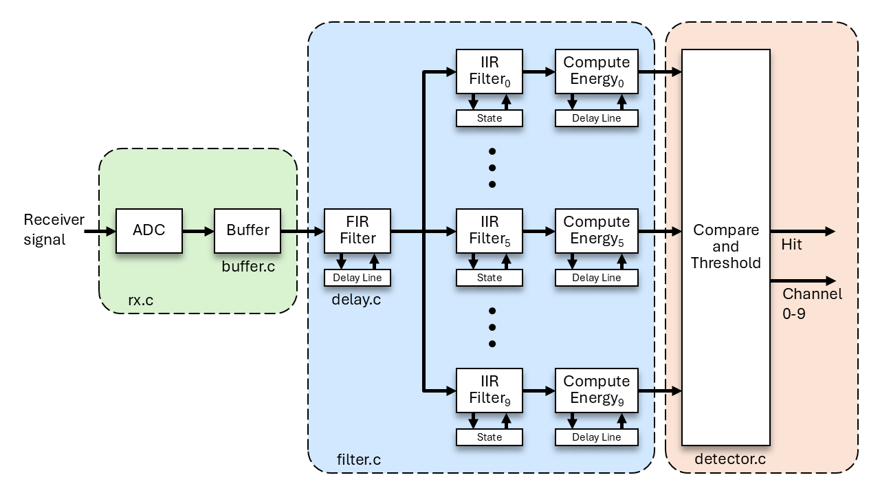
In this task you will finish implementing the receive path of your laser-tag system, which includes a circular buffer and a hit detector. The filter component of the receive path was implemented in Milestone 3, Task 1. An implementation of the receiver driver (rx) is provided for you. The receiver driver interacts with the ADC, which digitizes the amplified signal coming from the photodiode on your analog board. You will test each of these components with provided test code to verify correct operation. In a later milestone, you will be guided how to connect these components in a complete laser-tag system.
Components
- Circular Buffer: this buffer stores values digitized by the ADC.
- Receiver Driver: this driver digitizes an incoming analog signal and places the samples in the circular buffer.
- Hit Detector: this detector takes the current energy for each channel coming from the filter component and detects if a hit is present.
General Requirements
- Implement a circular buffer for storing values read from the ADC.
- Implement the hit detection algorithm.
- When implementing components, follow the descriptions given for each function in the header files.
- You must follow the coding standard.
- You must demonstrate the behavior of your components to the TAs using the provided test code.
Resources
Source Code
Note that the following files are provided in your ecen390 project directory. The test code is used to check the correctness of your code.
- ltag/main/buffer.h
- ltag/main/detector.h
- ltag/main/main_m3t3.c
- ltag/main/test/test_buffer.h
- ltag/main/test/test_buffer.c
- ltag/main/test/test_detector.h
- ltag/main/test/test_detector.c
You are expected to create and implement the following files. See the provided header files (.h) for a description of each function.
- ltag/main/buffer.c
- ltag/main/detector.c
When implementing each function, pay attention to the function descriptions in the header files. In fact, save lost points from the coding checker by copying the comments and function prototypes from the header files to your .c files to start your code. Also, you are likely to lose points from the coding checker if you modify the header files! So, don’t modify the provided header files.
Implementation
Circular Buffer
Specification
- Only use integer types (uint16_t, uint32_t, int16_t, etc.) in the implementation. DO NOT use float or double types!
- The buffer is cleared of any elements with
buffer_init(). - When adding a value to the buffer, the oldest value is overwritten if the buffer is full.
- When reading a value from the buffer, zero is returned if the buffer is empty.
- The capacity of the buffer in elements is returned with
buffer_size(). - The number of elements stored in the buffer is returned with
buffer_elements().
Detail
Implement a circular buffer in buffer.c that is dedicated to storing incoming integer data of type buffer_data_t.
A sketch is given below as a starting point for an implementation of buffer.c. You will need to finish the implementation. See this circular buffer article for implementation help.
#include "buffer.h"

#define BUFFER_SIZE 16384

typedef struct {
    uint32_t indexIn; // Points to the next open slot.
    uint32_t indexOut; // Points to the next element to be removed.
    uint32_t elementCount; // Number of elements in the buffer.
    buffer_data_t data[BUFFER_SIZE]; // Values are stored here.
} buffer_t;

volatile static buffer_t buf;

// Functions...
Do not implement the buffer component by shifting values in the data array. It will be too slow!
Hit Detector
Specification
- When the detector is first initialized, all channels are considered for hits. Assume the filter module is initialized previously.
- Frequency channels are ignored for hit detection if the corresponding element of a channel array is marked false when passed as an argument to
detector_setChannels(). - All channels are ignored if a global ignore-hit-flag is set with a call to
detector_ignoreAllHits(true). This is useful during periods of invincibility or during a lockout after a previous hit. - When a hit is detected, a global hit flag will be set and a global channel number will be set. These values can be retrieved with
detector_getHit()anddetector_getHitChannel(). - Once a hit is detected, no more hits can be detected until
detector_clearHit()is called. - Hit detection is skipped if the ignore-hit-flag is set or if a previous hit has not been cleared.
Detail
Detecting “Hits”
Having completed the filter component, you have code that can compute the total energy that passes through each of your IIR-based bandpass filters. Now what? Here are some considerations.
- You could always select the bandpass filter output that contains the maximum energy relative to the others. Unfortunately this simple scheme won’t work because it would always detect a “hit” of some sort, even when no one is shooting at you. Due to various noise sources, there will always be some energy in at least some of the frequencies, even when no one is shooting at you.
- You could select the frequency that contains an energy value that is above some threshold. This “kind of” works; however, it is difficult or impossible to come up with a threshold that works in enough situations. For example, let’s say you perform some experiments in indoor light with the two tag units spaced apart by about 10 feet. At this distance, you set the threshold so that “hits” are only detected when the computed energy is above the threshold. OK so far. Now you move the tag units so that they are 20-feet apart. Now, when you press the trigger, nothing happens because the energy numbers across all frequencies are not above the threshold. You can lower the threshold to increase sensitivity and detect “hits” at greater distances. However, at some point you will begin to detect noise (from your amplifier circuitry, from the ambient lighting, etc.) as a “hit”. Clearly, just comparing the energy in the bandpass filter outputs to a fixed threshold won’t work very well.
A Hit-Detection Algorithm
We will use an algorithm that adjusts the threshold based upon the current energy contained in the outputs from all 10 bandpass filters.
The detection algorithm consists of the following steps:
- After running all of the filters and computing the energy for each bandpass filter output, sort the energy values in ascending order according to their magnitude. Just use a selection sort or an insertion sort algorithm to do the sorting.
- Select the median value. Selecting the median value is simple once you have sorted the energy values – the median value is simply the value “in the middle” of the set of sorted values. For our system, we have 10 energy values; once they are sorted in ascending order, the median value is either the 5th or 6th element according to the sorted order. Everyone should sort values in ascending order and select the 5th value (C array index 4) for consistency.
- Multiply the median value with a factor to compute a threshold. This computed threshold should be high enough to reject noise and avoid false “hits” but should be low enough to detect hits from a distance of 40 feet or so. You will compute a default threshold factor through experimentation in Milestone 4. Why use a threshold factor? Because it can adjust for the different sensitivities in everyone’s analog board.
- Find the bandpass filter that contains the maximum energy (this is easy to do once you have sorted the values). If the maximum energy exceeds the threshold (median_value * threshold_factor), you have detected a hit.
Pro Tip: When sorting energy values, sort a separate array containing the indices of the original array. If you sort the energy values themselves, you will not know what frequency channel the value originally came from. Comparing the high energy value with an unsorted copy of the energy values to find the channel doesn’t work either, so don’t try it. Below is a sketch of a custom sort function that sorts the index array and not the energy values.
// Sort the indices idx[] that reference array s[] in ascending order.
// Does not modify s[].
// idx[] and s[] are of length n.
static void sort(uint16_t idx[], filter_data_t s[], uint32_t n)
{
}
After the sort, you can identify the median energy channel with idx[4] and the median energy value with energy[idx[4]].
Hit-Detection Algorithm Example
Here is an example of the hit-detection algorithm in operation. Assume the threshold factor = 5. Let’s say that we retrieve the current energy values for all 10 frequencies using the previously-implemented function: filter_getEnergyArray(). The retrieved energy values for the 10 frequencies for this example are:
- energy[0]: 150
- energy[1]: 20
- energy[2]: 40
- energy[3]: 10
- energy[4]: 15
- energy[5]: 30
- energy[6]: 35
- energy[7]: 15
- energy[8]: 25
- energy[9]: 80
After sorting in ascending order, we get the following:
- energy[3]: 10 (#1)
- energy[7]: 15 (#2)
- energy[4]: 15 (#3)
- energy[1]: 20 (#4)
- energy[8]: 25 (#5)
- energy[5]: 30 (#6)
- energy[6]: 35 (#7)
- energy[2]: 40 (#8)
- energy[9]: 80 (#9)
- energy[0]: 150 (#10)
The median value (sorted element #5) is 25 from the bandpass filter for frequency 8. For this example, that would mean that you would only detect hits for values that are over the threshold value of 25 (median value) * 5 (threshold factor) = 125. The bandpass filter for frequency 0 has the maximum energy value (150) which is greater than 125 so we would detect a hit.
Let’s run the detector again with another set of data. After sorting, the energy values from the bandpass filter outputs are as follows:
- energy[2]: 10 (#1)
- energy[1]: 25 (#2)
- energy[4]: 30 (#3)
- energy[7]: 30 (#4)
- energy[8]: 45 (#5)
- energy[6]: 50 (#6)
- energy[5]: 55 (#7)
- energy[3]: 65 (#8)
- energy[9]: 70 (#9)
- energy[0]: 150 (#10)
Our median value (element #5 in sorted order) = 45. We compute the new threshold by multiplying 45 * 5 (threshold factor) = 225. Our maximum energy value (150) is less than our computed threshold (225) so no hit is detected. The reason no hit is detected is because the maximum energy is not sufficiently greater than the energy contained in the outputs of the other bandpass filters.
These numbers are provided solely for example. The actual numbers you will encounter in your system will be quite different.
Receive Path
A function is needed that ties all the components of the receive path together. These components are the receiver driver, the filter stages, and the hit detector. The detector_run() function will implement the receive path.
When you invoke detector_run(), perform the following steps:
- Query the ADC receive buffer to determine how many elements it contains. Use
rx_get_count()for this. Call this amountadc_cnt. - Now, repeat the following steps
adc_cnttimes.- Get a sample from the ADC receive buffer using
rx_get_sample(). Place this value in a variable calledrawAdcValue. - Scale the integer value contained in
rawAdcValueto a floating-point number of typefilter_data_tthat is between -1.0 and 1.0. Store this value into a variable namedscaledAdcValue. The ADC generates a 12-bit output that ranges from 0 to 4095. 0 would map to -1.0. 4095 maps to 1.0. Values in between 0 and 4095 map linearly to values between -1.0 and 1.0. Note: this is a common source of bugs. Carefully test the code that does this mapping. - Invoke
filter_addSample(scaledAdcValue). This provides a new input to the filter stages. - If
filter_addSample()returns true, meaning that decimation occurred and the filter stages were run, then do the following:- Get a copy of the energy values with a call to
filter_getEnergyArray(). - Pass these energy values to the function
detector_checkHit()to check for a hit. There is no need to take action here if there is a hit since a user can retrieve the hit status later withdetector_getHit().
- Get a copy of the energy values with a call to
- Get a sample from the ADC receive buffer using
Assumptions:
- Reading from the ADC receive buffer is protected with a critical section. The provided implementation of the receiver driver complies with this assumption and protects all accesses to the buffer with critical sections.
- Draining the ADC receive buffer occurs faster than it can fill. When running the provided test code, the detector run time will be checked for compliance. The detector run time will be printed as
det:NN ms.
Other Help
FreeRTOS Software Timer
When using a FreeRTOS software timer, make sure to include the FreeRTOS header and the timers header at the beginning of your file. Also, make sure that you save a handle to the created timer globally so you can access it in other functions within the file. The callback function passed as an argument to xTimerCreate() must match the expected type. In the sketch below, the expire_actions() callback function is an example of this type.
#include "freertos/FreeRTOS.h"
#include "freertos/timers.h"

static TimerHandle_t timer; // Declare timer handle

// Callback function called when the timer expires
static void expire_actions(TimerHandle_t pt)
{
}
Test Code
To pass off this task, you must run your code with the provided test code. The test code calls functions in buffer.c and in detector.c. The test results are printed to the terminal window.
Before building the test code, first set the MILESTONE variable in ltag/main/CMakeLists.txt to “m3t3”.
set(MILESTONE "m3t3")
Then, to build and run the tests, type the following:
idf.py build
idf.py flash monitor
The test results printed to a terminal window on the host computer will look like this if everything passes:
******** test_buffer() ********
initialization test
half-fill and drain test
fill and drain test
push, pop, push, pop test
over-fill and drain test
push and over-drain test
******** test_buffer() Done ********

******** test_detector() ********
detector_checkHit() phase 1 test
detector_checkHit() phase 2 test
detector_checkHit() phase 3 test
detector_checkHit() phase 4 test
detector_checkHit() phase 5 test
detector_run() test, threshold:2048.0
hit_ch:0 energy:3.53e+01 pulse:21 ms det:11 ms
hit_ch:1 energy:6.43e+00 pulse:14 ms det: 7 ms
hit_ch:2 energy:1.73e+01 pulse:17 ms det: 9 ms
hit_ch:3 energy:2.36e+01 pulse:18 ms det:10 ms
hit_ch:4 energy:9.11e+01 pulse:28 ms det:15 ms
hit_ch:5 energy:1.81e+01 pulse:17 ms det: 9 ms
hit_ch:6 energy:4.92e+01 pulse:22 ms det:12 ms
hit_ch:7 energy:1.32e+01 pulse:16 ms det: 9 ms
hit_ch:8 energy:3.25e+01 pulse:20 ms det:11 ms
hit_ch:9 energy:9.64e+00 pulse:15 ms det: 8 ms
******** test_detector() Done ********
Pass Off and Code Submission
- You will show the TAs how your code behaves when running the provided test code. The test results will be displayed in a terminal window on the host computer. Nothing is displayed on the laser-tag unit LCD.
- You will submit your source code by doing the following:
- From the top-level directory (e.g., ecen390), run
./check_and_zip.py m3t3. - The resulting .zip file will be in the top-level directory. Submit that to Learning Suite.
- Submit only one .zip file per group. Both group members will receive credit.
- From the top-level directory (e.g., ecen390), run