Trigger, Transmit Path, Timer
Table of contents
Overview
In this task you will implement a debounce state machine for the trigger, a transmitter driver, and a shot counter that will keep track of the number of shots remaining. Additionally, you will implement a timer to flash LEDs when a hit is detected. You will test each of these components with provided test code to verify correct operation. In a later milestone, you will be guided how to connect these components in a complete laser-tag system.
Components
- Trigger Debounce: this state machine debounces a trigger press, which will be used to activate the transmitter driver.
- Transmitter Driver: this driver generates a square-wave signal on a GPIO pin at a user selectable frequency.
- Shot Counter: this counter keeps track of the number of shots remaining.
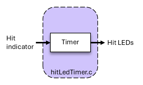
- LED Timer: this timer lights up the hit-indication LEDs on the laser-tag unit for 1/2 second each time a hit is detected.
![]()
General Requirements
- Implement the trigger debounce state machine using the approach taught in ECEN 330.
- Implement the transmitter driver.
- Implement a shot counter with reload capability.
- Implement the hit LED timer.
- When implementing components, follow the specifications.
- You must follow the coding standard.
- You must demonstrate the behavior of your components to the TAs using the provided test code.
General Notes
- Transmitter Frequencies: Use the frequencies listed in config.h:
{1250, 1481, 1739, 2000, 2353, 2667, 3077, 3333, 3636, 4000} - Transmitter Pulse Length: 200 ms.
- System Tick Rate: 25 Hz (40 ms period).
- Hit LED Flash Time: 1/2 second.
Only use integer types (uint16_t, uint32_t, int16_t, etc.) in these components. DO NOT use float or double types! If you use them in your tick functions, interrupt handlers, or timer event callbacks, you may see very strange behavior in your system.
Resources
- ESP32 GPIO driver
- ESP32 GPIO example
- ESP32 LED Control driver
- ESP32 LEDC example
- Pointers to functions
- FreeRTOS software timer
- Duty cycle
Source Code
Note that the following files are provided in your ecen390 project directory. The test code is used to check the correctness of your code.
- ltag/main/trigger.h
- ltag/main/tx.h
- ltag/main/shot.h
- ltag/main/hitLedTimer.h
- ltag/main/main_m3t2.c
- ltag/main/test/test_trigger.h
- ltag/main/test/test_trigger.c
- ltag/main/test/test_tx.h
- ltag/main/test/test_tx.c
- ltag/main/test/test_shot.h
- ltag/main/test/test_shot.c
- ltag/main/test/test_hitLedTimer.h
- ltag/main/test/test_hitLedTimer.c
You are expected to create and implement the following files. See the provided header files (.h) for a description of each function.
- ltag/main/trigger.c
- ltag/main/tx.c
- ltag/main/shot.c
- ltag/main/hitLedTimer.c
When implementing each function, pay attention to the function descriptions in the header files. In fact, save lost points from the coding checker by copying the comments and function prototypes from the header files to your .c files to start your code. Also, you are likely to lose points from the coding checker if you modify the header files! So, don’t modify the provided header files.
Implementation
Trigger Debounce
Specification
- The trigger state machine must debounce both the press and the release of the trigger switch (see Algorithm).
- The GPIO pin connected to the trigger switch is given as a parameter to
trigger_init(). - You read the current status of the trigger switch by reading the level of the connected GPIO pin.
- Use the ESP32 GPIO driver to get the level of the trigger pin.
- The trigger state machine recognizes the press of the trigger after the press has been debounced.
- The trigger state machine will not recognize another press of the trigger until the trigger has been released and debounced.
- When transitioning from a released to a pressed state, a “pressed” callback function is called.
- When transitioning from a pressed to a released state, a “released” callback function is called.
Detail
In trigger_init(), make sure that you configure the specified GPIO pin properly as an input. You may want to consider using the gpio_reset_pin() and gpio_set_direction() functions. Once the pin is initialized you can use gpio_get_level() to read the trigger position in the tick function. See this ESP32 GPIO example.
The trigger component uses callback functions to notify a user when the trigger has been pressed or released. The function to be called must be “registered” by the user with the trigger component and saved for later use. This is done by passing a function pointer to a user function (outside of trigger.c) as an argument to the trigger_register_...() functions. These trigger register functions should only be called by an external user of the trigger component and not from within. You will need to create global variables to save the function pointer arguments. If a callback function has not been registered, then no function should be called for that event. See this reference on Pointers to functions if needed.
Algorithm
Mechanical switches are imperfect when operated. When pressed or released they often “bounce” between closed and open states for a short period of time (10 milliseconds or so). For example, assume that a switch is wired such that it is read as a ‘1’ when pressed and read as a ‘0’ when released. If you continually read the switch when it is first pressed, you may read the switch initially as a ‘1’ but then a few milliseconds later, read it as ‘0’, then ‘1’, then ‘0’ and so forth. This process may repeat itself a few times until the output of the switch becomes completely stable. When a switch is initially pressed (or released) and quickly changes values, we say that the switch “bounces”.
We want our laser tag system to deliver exactly one shot for each press/release of the trigger. The easiest way to debounce a switch is to use a state machine that, in turn, uses a delay to determine when the switch has stopped bouncing. Here is a simple algorithm you can implement in a state machine and use to detect when a switch has stopped bouncing. It assumes that it will take no longer than 40 ms (one tick at the system tick rate) for the switch to stop bouncing. This is a reasonable assumption for a switch that is in good working order.
- Step 1: Wait until you detect a press of the switch.
- Step 2: Once you detect the press of the switch, keep track of the elapsed time.
- Step 3: If the switch changes value before the debounce time period is reached, reset the elapsed time and go to Step 1.
- Step 4: If the debounce time period is reached and the switch has not changed value, assume that the switch is debounced.
You need to use this process for both the press and release of the switch. A state machine with four states is a good choice, two for the press and two for the release. As a suggestion, draw a state diagram beginning with labeled circles for your states and then draw the transitions between states. Finally, list any actions associated with a state.
The logic level for the trigger switch in the laser-tag unit is inverted from the example above. The trigger position is read as a ‘0’ when pressed and read as a ‘1’ when released.
Transmitter Driver
Specification
- The transmitter driver generates a square-wave signal on a GPIO pin using the LED PWM (pulse width modulation) Controller on the ESP32.
- The GPIO pin connected to the power LED is given as a parameter to
tx_init(). - Configure the ESP32 LED Control driver to generate the signal on a GPIO pin.
- A call to
tx_emit()is used to start and stop generating a signal for indefinite time periods. - Each time the transmitter driver is activated with a call to
tx_pulse(), it must generate the signal for the specified duration in ms. - Use a FreeRTOS software timer to determine the pulse time period.
- The transmitter driver must be capable of generating signals between 1 and 5 kHz.
- You set the signal frequency in Hertz with
tx_set_freq(). - All generated signals must have a 50% duty cycle.
- The driver must ensure that the transmit GPIO pin is set to a level of ‘0’ when inactive. Otherwise, the power LED connected to the transmit GPIO pin will constantly illuminate.
Detail
In tx_init(), configure an instance of an LEDC timer and an LEDC channel. This ESP32 LEDC example shows how to use the PWM hardware to generate a signal. The following configuration values are known to work well for the transmitter driver. Initially, set the duty cycle to 0% so that the transmitter is turned off.
ledc_timer_config_t members
- speed mode: LEDC_LOW_SPEED_MODE
- timer number: LEDC_TIMER_0
- duty resolution: LEDC_TIMER_8_BIT
- initial frequency (Hz): 1000
- clock configuration: LEDC_AUTO_CLK
ledc_channel_config_t members
- speed mode: LEDC_LOW_SPEED_MODE
- channel: LEDC_CHANNEL_0
- timer select: LEDC_TIMER_0
- interrupt type: LEDC_INTR_DISABLE
- GPIO number: <the GPIO pin number passed to
tx_init()> - duty cycle: 0
- high point: 0
Also, tx_init() must create an instance of a FreeRTOS software timer using xTimerCreate(). Configure the timer to be a one-shot timer. See this FreeRTOS software timer reference for an example of how to initialize and use the timer.
Signal generation is turned on and off with tx_emit(). The duty cycle is set to 50% to turn on the transmitter and to 0% to turn off the transmitter. Use ledc_set_duty() to set the duty cycle. A 50% duty cycle can be specified with the following macro where res is the duty resolution in bits (use 8 in this case):
#define LEDC_DUTY_50(res) ((1U<<((res)-1))) // Set duty cycle to 50%
When implementing tx_pulse(), you can call tx_emit(true) to start generating a signal. In addition, start a timer for the pulse duration that has an expire action (a callback) that will stop the signal generation with a call to tx_emit(false). Use xTimerChangePeriod() to set the timer period. The tx_pulse() function should return immediately after starting the timer and signal generation, and not wait for the timer to expire.
Shot Counter
The shot module manages the shot count and can be used to support laser tag with a clip that contains N shots. Once a player has fired N shots they must wait S seconds for the clip to auto reload. The player may force a reload of the clip at any time by pulling and holding the trigger for S seconds (if the clip contains shots, the initial press of the trigger will fire a shot).
Specification
- During initialization, the shot count is set to the maximum count N. Also, a reload timer is created.
- The shot count is decremented with
shot_decrement()(when a user fires a shot) and can be reloaded after a delay (S). - A call to
shot_timer_start()initiates a timer that runs once for the period specified inshot_init(). - At timer expiration, the shot count is reloaded to the maximum count and the “reload” callback function is called.
- The timer can be stopped before expiration with a call to
shot_timer_stop(), thus preventing a reload of shots.
Detail
Use a FreeRTOS software timer to implement the reload timer. Configure the timer to be a one-shot timer with the period specified as a parameter in shot_init().
The shot component uses a callback function to notify a user when a reload occurs. The function to be called must be “registered” by the user with the shot component and saved for later use. This is done by passing a function pointer to a user function (outside of shot.c) as an argument to shot_register_reload(). This shot register function should only be called by an external user of the shot component and not from within. You will need to create a global variable to save the function pointer argument. If a callback function has not been registered, then no function should be called for that event. See this reference on pointers to functions if needed.
The expire_actions() timer callback function described above should call the shot callback function to notify the user of the reload event and set the shot counter back to the maximum count.
LED Timer
Specification
- When the LED timer is activated, it must illuminate the hit LEDs for the time period specified in the call to
hitLedTimer_init(). - The GPIO pin connected to the hit LEDs is also given as a parameter to
hitLedTimer_init(). - Use a FreeRTOS software timer to determine the active time period.
- A call to
hitLedTimer_start()activates the timer or restarts it from the beginning if currently active. - The default color for the LEDs when the timer is inactive is set with a call to
hitLedTimer_setColor(). - The color of the LEDs when the timer is active is set with a call to
hitLedTimer_setHitColor(). - When the timer has expired and is no longer active, the LEDs must be set back to the default color.
- If not specified, the default color is BLACK and the hit color is WHITE.
Detail
In hitLedTimer_init(), call neo_init() to initialize the NeoPixel driver. Make sure the LEDs are turned off (set to BLACK). Also, create an instance of a FreeRTOS software timer using xTimerCreate(). Configure the timer to be a one-shot timer with the period specified as a parameter in hitLedTimer_init().
Use neo_write() from the neo component to set the color of the NeoPixel LEDs. See the neo.h header file for a description of the functions. Four NeoPixel LEDs are integrated onto the laser-tag digital board and are connected serially. Each are individually addressable. Two are located on the front side of the board and two on the back side. Use a couple of pixel arrays to hold the colors, 3 bytes for each NeoPixel.
#define PIXEL_SZ 3
#define PIXEL_CNT 4
static uint8_t pixels_def[PIXEL_SZ*PIXEL_CNT]; // Default color
static uint8_t pixels_hit[PIXEL_SZ*PIXEL_CNT]; // Hit color
Because of default task priorities in FreeRTOS, the function xTimerIsTimerActive() does not reliably report the active status of a timer and should not be used to implement hitLedTimer_running(). Instead, use a volatile global boolean flag for tracking when the timer is active. Set the value as needed inside of the LED timer component.
Other Help
FreeRTOS Software Timer
When using a FreeRTOS software timer, make sure to include the FreeRTOS header and the timers header at the beginning of your file. Also, make sure that you save a handle to the created timer globally so you can access it in other functions within the file. The callback function passed as an argument to xTimerCreate() must match the expected type. In the sketch below, the expire_actions() callback function is an example of this type.
#include "freertos/FreeRTOS.h"
#include "freertos/timers.h"

static TimerHandle_t timer; // Declare timer handle

// Callback function called when the timer expires
static void expire_actions(TimerHandle_t pt)
{
}
Macros for Debug
The following DPRINTF macro is a helpful alternative to the normal printf function call since it can be switched off by making sure DEBUG is not defined. If you have many DPRINTFs sprinkled throughout your code, you can turn them all off at once while still leaving them in your code for later use.
The DPCHAR macro is a low-overhead way to print a character to the console. The macros can be left in the code for later test and debug, but all of them can be disabled when running under normal use by not having DEBUG defined (commended out).
Place the following code in your .c file near the top, but below other #include lines. Use DPRINTF just like you would printf.
// Uncomment for debug prints
// #define DEBUG

#if defined(DEBUG)
#include <stdio.h>
#define DPRINTF(...) fprintf(stderr, __VA_ARGS__)
#define DPCHAR(ch) fputc(ch, stderr)
#else
#define DPRINTF(...)
#define DPCHAR(ch)
#endif
Be aware that if you print within your tick functions and your tick functions are in turn called from a timer ISR (interrupt service routine), you may get timer overruns and unusual behavior. A print function can take a long time to execute relative to the timer period.
For more ideas on getting visibility into the operation of your code, here’s a link to a page describing how to debug state machines.
Test Code
To pass off this task, you must run your code with the provided test code. The test code calls functions in trigger.c, tx.c, shot.c and in hitLedTimer.c. The trigger test, will flash the NeoPixels as the trigger is pressed ten times. When the NeoPixels turn red, the trigger disable function is being tested. Keep operating the trigger during this period. The transmitter and shot test results are printed to the terminal window. Finally, the hit LED timer should flash the NeoPixels for one-half second on and off.
Before building the test code, first set the MILESTONE variable in ltag/main/CMakeLists.txt to “m3t2”.
set(MILESTONE "m3t2")
Then, to build and run the tests, type the following:
idf.py build
idf.py flash monitor
The test results printed to a terminal window on the host computer will look like this if everything passes:
******** test_trigger() ********
DUDUDUDUDU
trigger disable
trigger enable
DUDUDUDUDU
******** test_trigger() Done ********

******** test_tx() ********
tx_emit() test
freq:1249.7 Hz, duty:50.0%, pulse:100.0 ms
freq:1480.7 Hz, duty:50.0%, pulse:100.0 ms
freq:1738.5 Hz, duty:50.0%, pulse:100.1 ms
freq:1999.8 Hz, duty:50.0%, pulse:100.0 ms
freq:2352.6 Hz, duty:50.0%, pulse:100.3 ms
freq:2666.3 Hz, duty:50.0%, pulse:100.1 ms
freq:3076.5 Hz, duty:50.0%, pulse:99.8 ms
freq:3332.5 Hz, duty:50.0%, pulse:100.2 ms
freq:3635.0 Hz, duty:50.0%, pulse:100.1 ms
freq:3999.0 Hz, duty:50.1%, pulse:100.3 ms
tx_pulse() test
freq:1249.8 Hz, duty:50.0%, pulse:195.2 ms
freq:1480.7 Hz, duty:50.0%, pulse:197.2 ms
freq:1738.7 Hz, duty:50.0%, pulse:199.0 ms
freq:1999.6 Hz, duty:50.0%, pulse:191.0 ms
freq:2352.5 Hz, duty:50.0%, pulse:193.0 ms
freq:2666.7 Hz, duty:50.0%, pulse:194.6 ms
freq:3076.3 Hz, duty:50.0%, pulse:196.7 ms
freq:3332.3 Hz, duty:50.0%, pulse:198.7 ms
freq:3635.4 Hz, duty:50.0%, pulse:190.4 ms
freq:3999.2 Hz, duty:49.9%, pulse:192.3 ms
******** test_tx() Done ********

******** test_shot() ********
shot_init() test
shot_decrement() test
shot_timer_start() _stop() test
shot_register_reload() and timer test
shot canceled timer test
******** test_shot() Done ********

******** test_hitLedTimer() ********
******** test_hitLedTimer() Done ********
Pass Off and Code Submission
- You will show the TAs how your code behaves when running the provided test code. The test results will be displayed in a terminal window on the host computer. You will also show the TAs the information displayed on the laser-tag unit LCD.
- You will submit your source code by doing the following:
- From the top-level directory (e.g., ecen390), run
./check_and_zip.py m3t2. - The resulting .zip file will be in the top-level directory. Submit that to Learning Suite.
- Submit only one .zip file per group. Both group members will receive credit.
- From the top-level directory (e.g., ecen390), run