Your RISC-V processor will have a precompiled built-in program within the instruction memory when you run the implementation tools in Vivado. It will be necessary for you to change the program running on your processor with your own programs and programs provided by the labs. This document describes how you can change the RISC-V program that is embedded inside your processor.
Changing the bitstream involves the following four steps that are described in detail below:
- Create an initial working bitstream with default program
- Generate a “checkpoint”
.dcpfile of your working processor - Create and compile your new assembly language program
- Run the update memory insertion script on the checkpoint file
1. Create an initial working bitstream with default program
Before changing the program on your processor, you need to create an initial bitstream that contains your processor executing some default program. A default program is given to you as part of the laboratory instructions and you should generate a bitstream that contains this program and verify that the bitstream is working properly. Do not proceed to the next steps until you know you have a working processor bitstream.
2. Generate a “checkpoint” .dcp file of your working processor
In order to modify the program in the processor, you need to generate a “checkpoint” file (.dcp file) of your current processor design.
This file includes all the details of your placed and routed processor design and is needed by future steps of this process for changing the contents of the memories inside of your FPGA.
To create the design checkpoint file, open the Vivado project with your processor system.
You should have already completed the place and route implementation steps of your design as part of Step 1.
Once you have opened Vivado, you need to “open” the implemented design.
You can do this from the Vivado GUI by selecting “Open Implemented Design” (on the left side under the “Implementation” section of the flow navigator).
Alternatively, you can type the following command in the TCL command window: open_run impl_1.
When the implemented design is open you should see a layout of your design within the FPGA fabric.
With the design implementation open, you can create the checkpoint file by selecting the “File->Checkpoint->Write” commmand in the Vivado GUI.
A dialog box will open up and ask you for the directory and name of the .dcp file.
Place this file in a convenient location as it will be used every time you want to change the program memory and generate a new bitstream.
You can also create a checkpoint file from the TCL command window as follows:
write_checkpoint <.dcp filename> -force
You should have a file with a .dcp extension when you are done with this step.
3. Create and compile your new assembly language program
The next step is to assemble your assembly language program. Write your assembly language program and debug your code to remove all errors.
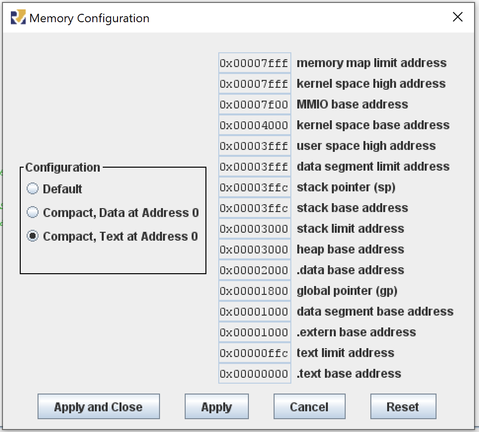
When creating programs for the RISC-V system on your FPGA you will need to change the memory organization of the RISC-V system. We are using a much smaller memory model and will have different locations for our .text and .data segments. We want to use the “Compact, Text at Address 0” memory configuration. For this memory configuration, the .text segment starts at address 0x00000000 and the .data segment starts at 0x00002000. The following command demonstrates how to assemble your assembly language program, and generate the memory files for use in your design:
java -jar ../resources/rars1_4.jar mc CompactTextAtZero a \
  dump .text HexText program_text.mem \
  dump .data HexText program_data.mem \
  dump .text SegmentWindow program_s.txt \
  program.s
The following example includes the previous example but placed in a single line for easier copying and pasting.
java -jar ../resources/rars1_4.jar mc CompactTextAtZero a dump .text HexText program_text.mem dump .data HexText program_data.mem dump .text SegmentWindow program_s.txt program.s
Instructions for generating these files with the GUI are provided at the end of this document.
4. Run the update memory insertion script on the checkpoint file
The final step to update your bitfile with new software code is to run a Vivado script that loads your design checkpoint, parses your data files, inserts the data into the design, and then generates a bitstream.
A script resources\load_mem.tcl has been written for you that will perform all of these steps.
This script is run from a command line window outside of Vivado. Vivado is called in “batch” mode to run a script that generates the bitfile. The following command executed from the linux command line demonstrate how to run this command:
vivado -mode batch -source ../resources/load_mem.tcl -tclargs updateMem <checkpoint .dcp filename> <.text memory file> <.data memory file> <new bitstream filename> [optional .dcp file]
This command has a number of arguments that you must customize based on your situation:
- <checkpoint filename>: The name of the new checkpoint file you created in the previous step
- <.text memory file>: The instruction memory (‘text’) file of your new program generated by the assembler
- <.data memory file>: The data memory file of your new program generated by the assembler
- <new bitstream filename>: The filename of the new bitstream file this command creates
- optional .dcp file: This program can optionally create a new .dcp file that contains the contents of your updated program. This will be necessary when you want to make additional changes to the bitfile such as changing the font memory or background character memory
If you are successful with this step then you will have a new .bit file that contains your updated RISC-V program.
Using the RARS GUI
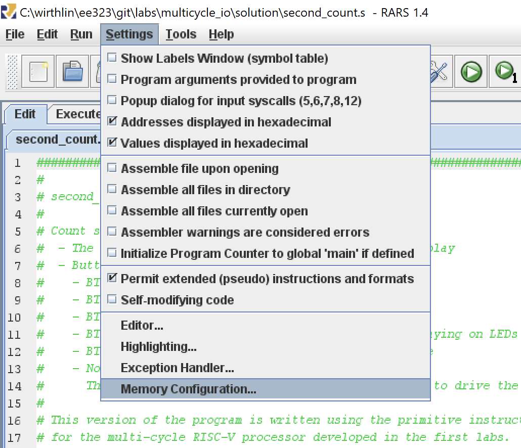
To change the memory configuration to the “Compact, Text at Address 0” configuration, follow these steps on the RARS gui:
- Select “Settings->Memory Configuration” menu option
- Click the “Compact, Texxt at Address 0” option
- CLick “Apply and Close”
Screen shots of these steps are shown below.
Create text memory
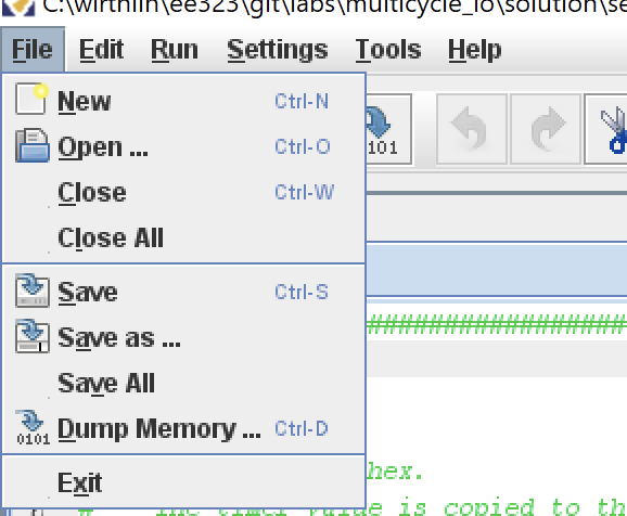
After you program has succsesfully been assembled and the memory configuration properly set, you need to create the memory text files for both the instruction memory and the data memory. These files will be represented as text hex words. To generate these files, select the “File->Dump Memory” menu option. Note that this option is only available after the asembly language program ahas bene assembled.
The “Dump Memory to File” dialog box will open up giving you different options for dumpting the memory to a file. The dialog box has two different options that can be set. The left option is the “Memory Segment” and allows you to choose to dump the .text (instructions) or .data. The right option is the “Data Format” and allows you to select the format to dump the data. The format needed is the “Hexadecimal Text”. After choosing the appropriate options, click “Dump to File…” and choose a name for the file. It is helpful to use the same prefix for both the .text and .data files (such as ‘myfile_text.txt’ and ‘myfile_data.txt’ for an assembly file named ‘myfile.s’).
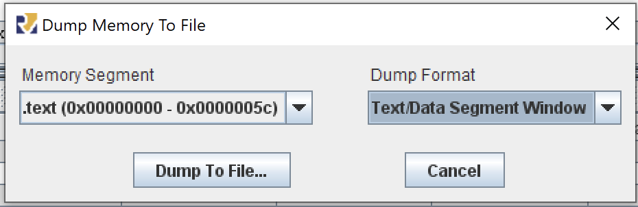
Although not required, it is also helpful to generate a debug file that summarizes the instruction memory, its labels, and addresses. This can be created by selecting the “Text/Data Segment Window” in the format option.