Table of Contents
Lab 12 - Final Project
For this laboratory you will write a custom program for your RISC-V processor that implements a simple game on the Basys 3 board.
 Avg Hours: ? (Winter 2022)
Learning Outcomes
- Demonstrate understanding of RISC-V assembly language programming
- Create custom software that controls the I/O interfaces of the FPGA system
Preliminary
In this final laboratory you will be able to create a custom program that executes on your RISC-V processor and that implements some interactive activity such as a game. This preliminary will guide you through a number of steps that you will need to prepare you to complete this custom program. The interactive program you create for this lab should be creative and you should try to choose something that interests you and ideally entertaining. The following suggestions may help you come up with some ideas:
- A “paint” program that allows you to move the cursor around the screen using the buttons and then place or “paint” the custom character at the cursor location
- A simple Pong game that moves a ‘ball’ across the screen along with controllable paddles to hit the ball back and forth
- Draw a moving snake on the screen that reacts to the user’s buttons
- A simple Tetris game with rotating blocks falling down the screen
- A maze game where the player moves a block through a predetermined maze built from walls
- A Hangman game that requests letters from the user and builds a hangman guy as mistakes are made
Unlike the previous labs, you can complete this lab with a partner. You can split up the work involved with the custom project between two people. Note that submissions involving two people will be expected to be more complex than those submitted by individuals.
There are several additional capabilities and features of the I/O subsystem that will help you create a fun and interesting game. The preliminary will review several of these features.
Font ROM
The I/O system circuit provided in previous labs contains an internal memory used to store a “font” of characters available for display.
The contents of this memory are defined in a file found at: ./resources/iosystem/cores/vga/font_mem.sv.
This memory is “Read Only Memory” (ROM) and cannot be changed at run-time.
Each character is defined as an image that is 8 pixels wide and 16 pixels high.
The characters are defined with two colors: foreground and background (i.e., on and off).
The figure below demonstrates the definition of the character ‘A’ in this font using red pixels for the foreground and white pixels for the background:

The description of each character is defined within a text file that indicates which pixels are in the foreground (on) using a binary ‘1’ and which pixels are in the background (off) using the binary ‘0’. The following example demonstrates the text lines in this file that define the character ‘A’:
// code x41
00000000   // 0
00000000   // 1
00010000   // 2    *
00111000   // 3   ***
01101100   // 4  ** **
11000110   // 5 **   **
11000110   // 6 **   **
11111110   // 7 *******
11000110   // 8 **   **
11000110   // 9 **   **
11000110   // a **   **
11000110   // b **   **
00000000   // c
00000000   // d
00000000   // e
00000000   // f
Each line of the text file defines eight bits of one row of a character. There are 16 lines for each character along with comments (i.e., ‘//’) indicating what the character should look like. The characters are ordered by their ASCII value. The entire font is defined in this text file. Browse through this font ROM file and its contents to answer several questions in learning suite.
Determine the character represented by 0x18 in the file
What is the 8-bit binary value associated with line 7 of the 0x35 ASCII character (i.e., the number 5)?
You can modify the font memory to create new characters that are more useful for the game you create in this lab. You can come up with custom non-ASCII characters that are specific for your lab project. For this lab, you will be required to modify the font ROM to include new characters to represent unique figures for your final lab. The example below demonstrates a simple attempt at a Pac-Man character. Note that you can create larger images by using multiple unique characters side by side and above and below each other.
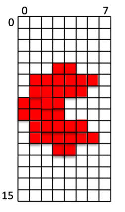
Binary file representation of the pacman character:
// custom character
00000000   // 0
00000000   // 1
00000000   // 2
00000000   // 3
00011000   // 4    **
01111110   // 5  ******
01111100   // 6  *****
11110000   // 7 ****
11110000   // 8 ****
01111100   // 9  *****
01111110   // a  ******
00011000   // b    **
00000000   // c
00000000   // d
00000000   // e
00000000   // f
Character Colors
As the preliminary of Lab #10 described, you have the ability to set a default foreground color and background color for the characters displayed on the screen. In addition to setting a default foreground/background color, it is also possible to set a custom foreground and background color for each character on the display. This allows you to create interesting colored characters with differing backgrounds that move around on the display.
To set a custom foreground and background color for a particular location on the VGA display, write a value to the character location with a non-zero color set in the upper 24 bits of the 32-bit word. If any bits [31:8] are non-zero, the VGA memory will store the store bits [19:8] into the foreground color for the character and store bits [31:20] into the background color for the character. The 32-bits used by the VGA character memory are defined as follows:
| Background Color | Foreground Color | Unused | Character Value |
|---|---|---|---|
| data[31:20] | data[19:8] | data[7] | data[6:0] |
For example, to write the character “!” (ASCII 0x21) with a red foreground color (0xf00) and a blue background color (0x00f), you would write the following value to the VGA display:
0x21 | (0xf00 << 8) | (0x00f << 20) = 0x00ff0021
To write the character “$” (ASCII 0x24) to the display using the default background and foreground colors instead of a custom color, you would write the following value to the VGA display:
0x24 | (0x000 << 8) | (0x000 << 20) = 0x00000024
Determine the 32-bit value needed to write the character ‘?’ with a background of yellow (0xff0) and a foreground of cyan (0x0ff)
Character Memory
The VGA display circuitry includes a character generator that will display characters in a grid of 80 columns by 30 rows. The initial contents of this character memory can be set to provide an interesting initial “background” to your display. The character memory file contains a sequential list of 32-bit hexadecimal numbers that each will be placed in the character memory in sequential order. The following text demonstrates the first lines of the “checker” memory background. The file format accepts c-style single line comments:
// Row 0
f000ff20  // 0,0
00ff0020  // 1,0
Several example background memory files have been provided for you in your lab files including: checker_mem.txt, random_mem.txt, and border_mem.txt.
Describe the details of the character located on row 12, column 27 in the “checker_mem.txt” file
New Pseudo Instructions
For your final project you will likely need to access a number of values in the data segment.
Accessing variables in the data segment will require you to use lw and sw instructions.
When accessing variables in the data segment you will want to use a register to hold the base address of the data segment (the examples I give you will use the ‘gp’ or x3 for the base address of the data segment).
You will also need to know the offset of the data variable from the base of the data segment, i.e., lw t0, <offset>(gp).
The assembler can help you figure out the offset from the base so you don’t have to figure it out yourself.
The following syntax can be used for a lw instruction: lw <destination register>, %lo(<VARIABLE_NAME>)(gp), where VARIABLE_NAME refers to the name in the data segment of the given variable.
The following example demonstrates this use:
lw t0, %lo(ENDING_CHARACTER)(gp)                   # Load character value to write

# Later in the code is a memory location reserved in the data segment for this value
.data

ENDING_CHARACTER:
    .word CHAR_C_YELLOW
Unfortunately there is not a similar syntax for store (sw) instructions and you will have to perform stores in the data segment using two instructions.
The first instruction is used to compute the address of the memory you want to store using the following pseudo instruction: addi t0, gp, %lo(FASTEST_SCORE).
This pseudo instruction adds the offset value of the data (FASTEST_SCORE in this case) to the base register (gp in this case) to create an address that points to the given data element.
After computing the new address, you can use the ‘sw’ instruction directly as follows sw t1, 0(t0).
The following example demonstrates how to perform this store:
addi t0, gp, %lo(FASTEST_SCORE)
sw t1, 0(t0)

# Later in the code is a memory location reserved in the data segment for this value
.data

FASTEST_SCORE:
    .word 0xffff
Answer the questions in the report to test your understanding of these pseudo instructions
Exercises
Before proceeding with your laboratory exercises, update your repository with the latest lab starter code.
Exercise #1 - I/O System Simulation
In this first exercise you will simulate your processor from the previous lab executing a program within the I/O system that writes to the VGA.
You will have a new top-level I/O design named ‘riscv_io_final.sv’ that will insert your processor from lab 11.
A simple test I/O program, final_iosystem.s, has been written that operates on the I/O system described above.
Begin this exercise by assembling this assembly language file and generating the .mem files used by Vivado as described by this tutorial.
Next, create a new project for this lab by executing the following script (included with the starter code) in Vivado (note that this command will fail if you have not compiled your assemly language program into .mem files):
source create_final_project.tcl
This script will add all of the HDL files you need to build your final processor as well as include the compiled memory files into your project.
This program is a simple game that will have you move the ‘A’ character using the buttons to the location of the ‘C’ character. The game will time how long it takes and highlight the LEDs when you reach a new best score. The ‘Z’ character is a block that you have to move around.
Simulate your system by executing the final_sim.tcl TCL script.
This script will drive the top-level I/O and press button right, wait for the button to propagate through the debouncer and then press the button down.
Review the simulation console to answer the questions about the tcl script execution in learning suite.
Exercise #2 - Download System
After verifying your processor works correctly with the I/O system, create a bitstream of your system and download it to your board. Before running the implementation step, run the following command to increase the button debounce time for the actual circuit implementation (a shorter debounce time is used by default to simplify the simulation).
set_property -name {STEPS.SYNTH_DESIGN.ARGS.MORE OPTIONS} -value { -generic DEBOUNCE_DELAY_US=150 } -objects [get_runs synth_1]
Also, create a “.dcp” file for your system as described in the following tutorial. You will need this .dcp file to update the program running on the system in later exercises. Carefully review the synthesis logs to see if there are any unusual synthesis warnings.
Summarize the utilized resources for your implemented design and determine the worst negative slack timing of your processor.
After generating the bitfile, download the bitfile onto your Basys3 board and play the “game” implemented in the precompiled program. Indicate the “time” it took you to move the ‘A’ character to the ‘C’ character as indicated by the seven segment display (convert the hex display to a decimal number).
Indicate your best game completion time.
Exercise #3 - Memory Update
In this exercise you will update the bitfile to include a modified font ROM to display different characters for the game. You will also modify the bitfile to change the default background for the game.
Font Memory Updates
Within the lab files is a new font file name game_font_mem.txt.
This font file has modified the shape for the ASCII characters ‘A’, ‘C’, and ‘Z’ to make the game in the previous exercise more interesting.
The following command demonstrates how you can modify your bitstream file to include the modified font characters.
A new file, font.dcp, is also created that you will use later in this exercise.
Note: You will need to create a checkpoint (.dcp) file to run this command as described in the update memory tutorial.
$ vivado -mode batch -source ../resources/load_mem.tcl -tclargs updateFont final_io.dcp game_font_mem.txt font.bit font.dcp
Download this bitfile and verify that your updated bitstream has the updated characters when you play the game.
Background Memory Updates
In addition to changing the font, you can change the default background or initial VGA memory to provide a different background that is more interesting.
To make it easier for you to create interesting backgrounds, a script (../resources/generate_background.py) has been created that converts a background from a text template file into the background memory.
A background template file background_game_template.txt has been given to you as an example.
Create a new background memory file named game_background.mem by running the script as follows:
python3 ../resources/generate_background.py background_game_template.txt game_background.mem
Create a new bitstream that includes this new background by running the following command:
$ vivado -mode batch -source ../resources/load_mem.tcl -tclargs updateBackground font.dcp game_background.mem back.bit back.dcp
Download this new bitstream to make sure that your bitfile has both the new font and the new background. Also, play the game with this new background and record your game completion time.
Indicate your game completion time with the modified background.
Custom Font and Background
Now that you know how to modify your bitstream with a new font and a new background, create your own modified font memory file named font_mem_mod.txt that changes the characters ‘A’, ‘C’, and ‘Z’.
In addition, create a new background memory file named background_mem.txt that provides a much different background than the one provided as an example.
Download your bitstream to make sure you have the updated characters and background.
You will need to include these files in your lab submission (your updated characters and background will be evaluated by the TAs by playing the game with your bitstream).
Note: You need to submit the memory file generated by the python script, not the ASCII character map file that you used to create the memory file.
Exercise #4 - Interactive Game
For your final exercise you will create a custom interactive game that uses the buttons and switches and displays the results on the VGA display. There is no new Verilog required for this exercise unless you need to resolve bugs not found in your processor from previous labs. The primary activity of this exercise is to write and debug the assembly language code needed to implement your interactive game. You will also need to create a custom background and font ROM. This program will be much more involved than any of the simple programs you have written so far. Most of the time spent on this lab will be writing and debugging your program.
The minimum requirements of your program are as follows:
- The primary user interface is the VGA display. Your project should involve writing characters to the display for the user to interact with.
- You must include at least six modified characters in the font ROM (12 if you have a partner). Your project font file should be named
project_font.txt. - You must be able to restart the game from scratch without having to download the bitstream. This means you need to have the ability to reset the state of the game so the user can play as many times as they like.
- You must create and use a stack and create at least four procedures that use the stack in your program.
- The program must have at least 128 instructions (256 for group projects) in a single assembly file named
project.s - The system must have a custom background display (named
project_background.txt) - The program must use at least three buttons
- Write something to the 7-segment display
- Use at least one LED
It is not acceptable to take the example game given in lab with a few minor tweaks. You may reuse much of the logic from the example game, but a new game must be written from scratch.
You will need to create a text file that includes a detailed description of your program named instructions.txt.
A template file instructions_templates.txt has been created for you as a template for this file.
Make sure you complete all of the entries from this template file.
Pass Off
To create your submission, make sure the following files are committed in your ‘lab12’ directory:
| Filename | Purpose |
|---|---|
| font_mem_mod.txt | Custom font memory file for Exercise #3 |
| background_mem.txt | Custom background memory file for Exercise #3 (not the ASCII character map file) |
| project.s | Project assembly language file |
| project_font.txt | Custom font file for your final project |
| project_background.txt | Custom background memory file for your project (not the ASCII character map file) |
| instructions.txt | Text file with project instructions |
Note: If you are working in a team, make sure both students submit the same files in their own repository.
Make sure you do not add unnecessary files (including Vivado project files) to your repository.
Test your submission by running the lab12_passoff.py pass-off script found in the starter code.
Review the instructions for submitting and passing off labs to make sure you have completed the lab properly.
How many hours did you work on the lab?
Provide any suggestions for improving this lab in the future