Table of Contents
Lab 9 - RISC-V Forwarding
For this laboratory you will modify your pipelined processor from the previous lab to implement forwarding and hazard detection/stalling.
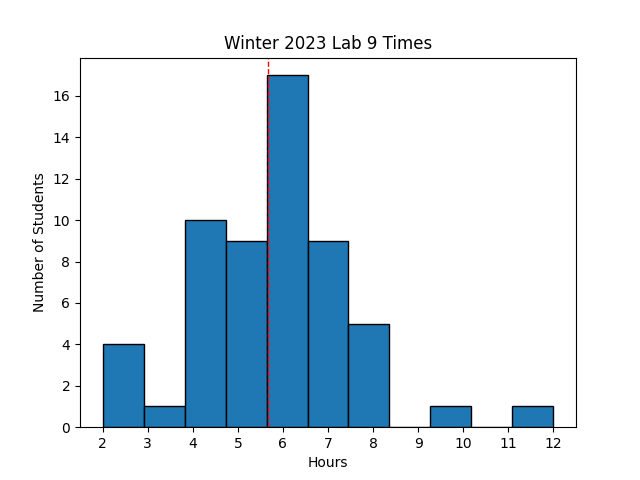 Avg Hours: 5.1, 5.1 (Winter 2022, 2021)
Learning Outcomes
- Understand how to modify your pipeline processor to implement forwarding
- Implement forwarding in your pipelined processor and verify its functionality
Preliminary
In this laboratory you will be modifying your pipelining processor to include forwarding. The preliminary exercises will help you understand important details about forwarding that you will need for implementing forwarding and stalling within your pipelined processor.
Forwarding
To help you prepare for this laboratory, review the following code and determine which instructions require forwarding. For each instruction, determine whether forwarding is used for each of the two ALU operands. Note that you need to account for bubbles inserted into the pipeline due to load-use hazards. For each operand, you will need to select one of the following options:
- No forwarding
- Forward from the MEM stage
- Forward from the WB stage Select “No Forwarding” if immediate data is used.
# Example #1
 1: addi x1, x0, 1
 2: add x2, x1, x1
 3: sub x3, x2, x1
 4: slt x4, x1, x2
 5: addi x5, x2, -3
 6: andi x5, x5, 0x7f0
 7: ori x5, x5, 0xf
 8: add x5, x5, x5
 9: addi x6, x0, 1024
10: add x8, x7, x2
11: sw x8, 4(x6)
An example of how you should respond for the first three instructions is shown below:
- Instruction 1 (addi x1, x0, 1)
- Operand 1 (Rs1): No forwarding
- Operand 2 (Rs2): No forwarding
- Instruction 2 (add x2, x1, x1)
- Operand 1: Forward from MEM stage
- Operand 2: Forward from MEM stage
- Instruction 3 (sub x3, x2, x1)
- Operand 1: Forward from MEM stage
- Operand 2: Forward from WB stage
Enter your response in Learning Suite.
Forwarding with Immediate Data
The description of forwarding in the textbook assumes that the instructions being executed are register instructions with two register operands. The logic given in the textbook does not take into account instructions that use immediate data instead of register data. Consider the following code sequence:
sub x2,x1,x3
addi x12,x5,2
In this example, the ‘addi’ instruction uses an immediate value of ‘2’ instead of a register for it’s second operand. The immediate value of 2 (0000 0000 0010 in binary) maps the value ‘00010’ in the same field as ‘rs2’ (bits [24:20]). If we don’t modify the forwarding logic, the forwarding logic as presented in the book will think that the ‘addi’ immediate instruction uses register 2 and will forward the results of the previous ‘sub’ instruction for its second operand instead of the immediate data.
You must amend the forwarding logic for the second operand (ForwardB) to check to see if the instruction uses immediate data. If you do not change this logic, then it is possible that your forwarding logic will replace the immediate data with data from an instruction further ahead in the pipeline.
Note that there are two different forwarding paths for the second ALU register (Rs2) read. The first path is used for the second operand of the ALU operation. It is this path that needs the immediate data rather than forwarded data. The second path is used for the write data during the MEM stage. This second path does not need to consider the immediate data and should use the conventional forwarding logic shown in the book. The diagram shown below demonstrates how to implement immediate forwarding properly as well as forwarding for the store data.
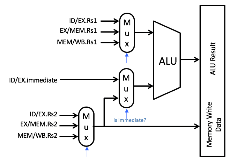
Modified Forwarding Logic Image
Determine the proper multiplexer settings for the ‘sw’ instruction in the following code sequence below.
# Example #2
addi x7, x0, 0x7fc
xor x8, x5, x3
sw x8, -4(x7)
Pipeline Hazards
There are a number of pipeline hazard conditions that cannot be resolved with forwarding. Instead, additional logic must be added in your pipeline to (1) detect the hazard condition, and (2) manage the pipeline properly to handle the hazard condition. The two hazards that you will address in this lab are the load-use hazard and control hazards (i.e. branches). Each of these will be discussed in more detail below.
Load-Use Stall
The “Load-Use” hazard is described in detail in the textbook (page 321-325). The load-use hazard occurs when a load instruction is followed by an instruction that needs the result of the memory load. As described in the textbook, the pipeline must stall and a “bubble” inserted into the pipeline to separate the “load” instruction from the next “use” instruction (see Figure 4.61 on page 324). The logic for detecting load-use hazards is described at the bottom of page 303. Once a ‘load-use’ hazard has been detected in the pipeline, the pipeline must stall the IF and ID stages of the pipeline and insert a ‘bubble’ into the EX stage. The following example demonstrates how a bubble is inserted and how stalls are implemented in the pipeline for the code example in Figure 4.61.
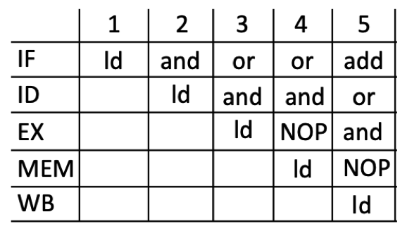
During clock cycle 3 of this pipeline example, the ‘load’ instruction is in the EX stage and the ‘and’ instruction is in the ID stage. It is during this clock cycle that the ‘load-use’ hazard detection logic will detect the hazard. Once the hazard is detected, the pipeline must stall the IF and ID stages, insert a bubble into the EX stage, and allow the MEM and WB stages to operate as usual. The status of each stage of the pipeline in clock cycle 4 is as follows:
- IF (stall): The PC has not been updated and it still points to the ‘or’ instruction,
- ID (stall): The next instruction has not been read and the current instruction still contains the ‘and’ instruction,
- EX (bubble): The control signals of this stage are set to zero preventing anything from happening down the pipeline (represented by a “NOP” instruction in the diagram).
- MEM (continue): The ‘ld’ instruction moves in the pipeline and performs its memory read operation, and
- WB (continue): The instruction preceding the ‘ld’ instruction (not given in the example) moves on to the WB stage.
To demonstrate your understanding of load-use hazards, identify which instructions below involve a load-use hazards. The first load-use hazard has been identified for you with a comment.
# Example #3
 1: lw x2,20(x1)
 2: add x4,x2,x5       # Load use hazard!
 3: lw x5,16(x4)
 4: sw x6,-4(x5)
 5: sub x4,x2,x6
 6: lw x7,-12(x4)
 7: xori x7,x4,0x1ff
 8: lw x8,256(x7)
 9: lw x9,0(x8)
10: and x10,x9,x8
11: lw x11,-8(x10)
12: andi x12,x10,0xff
Determine which instructions experience a load-use hazard.
There is a special ‘load-use’ that occurs when a store follows a load. For ‘sw’ instruction #4 above, there is a load-use hazard and a bubble will be inserted between the ‘lw’ instruction #3 and instruction #4. When instruction #3 is in the WB stage, instruction #4 will be in the EX stage.
Determine the proper multiplexer settings for the ‘sw’ instruction #4 from the code sequence shown above.
Control Hazards
The second type of pipeline hazards that we must address are control hazards or hazards that change the program counter (PC). For the processor we are building in this lab, control hazards occur with branches (the BEQ instruction). Section 4.8 of the textbook describes a number of ways to handle control hazards for branches. For this lab, you will implement the “predict not taken” approach that involves assuming that the branch is not taken and then “flush” the pipeline if the branch is actually taken. The discussion below will demonstrate how this will work.
The example below will use the following code segment as a reference. “beq” indicates a branch instruction in a program and the instructions “b+1”, “b+2”, and “b+3” refer to the instruction 1 after the beq, 2 after the beq, and so on. “Target” is the address that the branch will go to and the instruction “bt” represents the instruction at the branch target address. “bt+1” is the instruction following the branch target.
  beq Target
  b+1
  b+2
  b+3
  ...

Target:
  bt
  bt+1
  ...
The figure below describes how you should handle branches in the pipeline. The left table describes the operation of the pipeline when the branch is not taken and the table on the right describes the pipeline when the branch is taken.
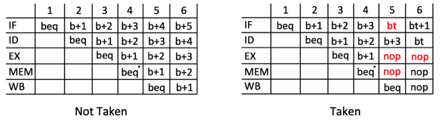
Not Taken
As the branch instruction proceeds through the pipeline, we will assume that the branch will not be taken by continuing to load the instructions that follow the branch in the program. In clock cycle 4, the branch is in the MEM stage and we will know whether the branch is taken or not (by the value of the ‘Zero’ signal). In the case that the branch is not taken, nothing is wrong and the pipeline continues to execute as normal. There is nothing that has to be done when the branches are not taken.
Taken
The challenging part of this approach is handling the case when the branch is taken. As discussed above, we don’t know whether the branch is going to be taken until clock cycle 4. At that point, we have three instructions in the pipeline that we don’t want to execute: “b+1” in EX, “b+2” in ID, and “b+3” in IF. If these instructions operate any further, they may change the stage of the processor in the MEM or WB stages. To prevent them from being executed we need to flush these instructions out of the pipeline before they process any further in the pipeline. Each of these instructions are flushed out of the pipeline as follows:
- Flushing the “b+2” instruction in the ID stage is relatively easy - we just insert a bubble into the EX stage like we did with the load-use stall. The same mechanism for inserting a bubble in the EX stage can be used to flush the instruction in the ID stage. The difference in this case (flushing) is that we are not stalling the ID stage - we let the ID stage proceed and just wipe out the instruction in the EX stage.
- Flushing the “b+1” instruction in the EX stage is also relatively easy - we just insert a bubble into the MEM stage. Additional logic is needed to support bubble insertion in the MEM stage just like that of the EX stage.
- Handling the “b+3” instruction in the IF stage is more difficult. Since we issued a request to fetch instruction “b+3” during clock cycle 4, we will receive the “b+3” instruction in the ID stage during cycle 5. To flush this instruction, we will have to wait a clock cycle and flush the instruction in cycle 6 when the branch is in the WB stage.
The code segment below contains branches and is given to test your understanding of how branches proceed through the pipeline using the assume branch NOT taken approach described above.
  ori x1, x0, 1
LOOP:
  beq x0,x1, DONE
  addi x2, x1, 2
  subi x3, x2, 1
  beq x0, x0, DONE
  andi x4, x3, 0xff
  ori x5, x4, 0x55
  xori x12, x12, x1
  addi x12, x12, x1
  addi x12, x12, x1
DONE:
  sub x6, x4, x3
  add x6, x6, x1
  beq x0, x0, DONE
  andi x1, x6, 0x3ff
  xori x2, x1, 0x3ff
  ori  x3, x2, 0x3ff
To complete this table, indicate which instruction is in which pipeline stage for all clock cycles in the table. You can ignore the instructions in the pipeline before the first ‘ori’ instruction. The first two clock cycles have been completed for you.
Emulate the execution of this instruction sequence by completing the pipeline table in learning suite.
| Cycle | IF | ID | EX | MEM | WB |
| 1 | ori | ||||
| 2 | beq | ori | |||
| 3 |
Special Case Load-Use/Branch Condition
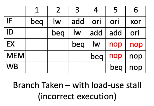
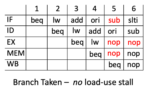
The approach described above to handle control hazards with the branches introduces a special case issue that must be addressed. This special case occurs when a ‘load-use’ stall occurs in the pipeline at the same time that a branch is taken. This happens when the branch taken condition is in the ‘mem’ stage, a load instruction is in the ‘ex’ stage, and an instruction is in the ‘id’ stage that uses the result of the load. In this unique case, we do not want to stall the ID and IF stages like we usually do for load-use stalls. Because the instructions immediately following a branch that is taken will not be executed we need to flush them out of the pipeline. If we stall the pipeline then we will not properly flush the pipeline as we should. The following code sequence demonstrates this special case condition:
  beq x0, x1, target
  lw x2, 0(x3)
  add x4, x2,x1        # Load-use
  ori x5, x4, x2
  xor x6, x4, x1
   .
   .
Target:
  sub x4, x2, x1
  slti x5, x3, x2
If the load-use stall occurs, the branch will not be taken as shown in the pipeline diagram below. In clock cycle 4, the ‘branch taken’ condition is identified and bubbles are inserted into the ‘ex’ and ‘mem’ stages. At the same time, a load-use condition is detected between the ‘lw’ instruction in the ‘ex’ stage and the ‘add’ instruction in the ‘id’ stage. Because of this load-use condition, the ‘id’ and ‘if’ stages are stalled. This stalling prevents the PC from being updated with the new branch target. In the next clock cycle (cycle 5), the pipeline continues with the incorrect instruction and the branch is not taken like it should.
To address this issue, you will need to modify your logic so that you do not stall the IF and ID stages under the load-use condition when a branch is being taken. Supporting this case is relatively easy by ignoring the load-use condition when there is a branch in the MEM stage that is taken. The following pipeline diagram demonstrates how the branch properly occurs when the load-use stall is ignored. Make sure your code is designed to handle this special case.
The logic to implement a load stall should include a number of logic clauses.
Determine the clauses that must be selected for the load-use condition in learning suite.
Exercises
Before proceeding with your laboratory exercises, update your repository with the latest lab starter code.
Exercise #1 - Forwarding Verilog
The primary task of this lab is to modify your pipelined RISC-V processor from the previous lab to include support for forwarding and stalls so that your processor can execute without any problems on any assembly code.
You should start this lab by copying your pipelined processor from the previous lab into a new file named riscv_forwarding_pipeline.sv.
It will be easiest to modify your existing pipeline processor than to start from scratch.
Note that the top-level interface has a new output port named ‘iMemRead’ and will be described later.
| Module Name: riscv_forwarding_pipeline | |||
|---|---|---|---|
| Parameter | Width | Default Value | |
| INITIAL_PC | 32 | 0x00400000 |
| Port Name | Direction | Width | Function |
|---|---|---|---|
| clk | Input | 1 | Global clock |
| rst | Input | 1 | Asynchronous Reset |
| PC | Output | 32 | Program Counter in IF stage |
| iMemRead | Output | 1 | Enable instruction memory reading |
| instruction | Input | 32 | Current instruction in the ID stage |
| ALUResult | Output | 32 | Value of the ALUResult in the EX stage |
| dAddress | Output | 32 | Address for the data memory |
| dReadData | Input | 32 | Value of the data read from he MEM stage |
| dWriteData | Output | 32 | Value of the write data in the MEM stage |
| MemRead | Output | 1 | Data Memory Read signal |
| MemWrite | Output | 1 | Data Memory Write signal |
| WriteBackData | Output | 32 | Value of write data in the WB stage |
There are a number of changes that you will need to make to your previous pipeline to support forwarding and address the pipeline hazards described earlier. The description below will describe the changes that will be needed.
Forwarding Logic
The primary modification to your simple pipeline from the previous lab is to add the logic to support forwarding in the EX stage. This logic includes the multiplexers used to steer the appropriate value to the ALU inputs (and memory write input) and the control logic to determine which value to forward. To support forwarding, you will need to add pipeline registers for Rs1 and Rs2 in the EX stage as shown in Figure 4.58 (page 321) of the textbook.
The logic needed for this detection and steering is discussed in the textbook and shown by the “forwarding unit” in Figure 4.56 (page 318). You will also need to implement the modified form of forwarding for the rs2 input and the memory read value as described above in the preliminary.
Hazard Detection Logic
The forwarding logic you create will be able to handle most data hazards. However, it will not be able to resolve the load-use hazard or the control hazards associated with branches. You will need to add logic to detect these hazards. The hazard conditions you need to detect include the following:
- load_use_hazard - Detects the presence of the ‘load-use’ hazard in the pipeline.
- branch_mem_taken - Detects that a branch is in the MEM stage and it is taken.
- branch_wb_taken - Detects that a branch is in the WB stage and it is taken.
Create new signals in your pipeline to detect each of the situations described above. You will use these signals to support the stalling of pipeline stages and the insertion of bubbles as described below. Note that you need to detect the special case when a branch is taken and a load-use hazard follows the branch (see the preliminary for details).
Stall and Bubble Insertion Logic
As described in the preliminary, the pipeline must be modified to support stalling of the pipeline and the insertion of pipeline bubbles when hazards exist. The only stages that need to be stalled are the IF and ID stages. Bubbles need to be inserted into the EX stage (for both load-use and branch hazards) and into the MEM stage for branch hazards. The discussion below describes how to modify your logic to perform this stalling and bubble insertion.
IF Stage Stall
Stalling the IF stage means preventing the PC from being updated. In the previous lab when one new instruction was issued each clock cycle, the PC was updated every cycle. In this lab, the PC update should not be updated when there is a load-use hazard. Modify your logic so that the PC is stalled (i.e., not updated) when there is a load-use hazard (stalls are not needed when there is a branch hazard). Modify your PC update logic so that it does not change when there is a load-use stall. This stalling is represented by the ‘loadPC’ signal (labeled ‘PCWrite’ in Figure 4.62 on page 325). When ‘loadPC’ is ‘1’ then the PC signal will be updated as in normal operation. When ‘loadPC’ is ‘0’, the PC should hold its current value and not update (i.e., IF stall).
ID Stage Stall
Stalling the ID stage means preventing a new instruction from being loaded into the current instruction in the ID stage. A new signal has been added to this module to allow you to prevent the instruction memory from reading a new instruction. The ‘iMemRead’ output signal is used to tell the instruction memory to perform an instruction read. Under most circumstances this signal should be set to ‘1’ indicating that a new instruction should be read. In the case of a ‘load-use’ hazard, however, this signal should be set to ‘0’ to tell the instruction memory not to change the instruction that was loaded the previous cycle. Create the logic for generating the ‘iMemRead’ signal as described here.
In addition to preventing the instruction memory from loading a new instruction, you should not copy the PC value in the IF to the ID pipeline register when the IF stage is stalled.
Inserting Bubbles in the Pipeline
Bubbles need to be inserted into the pipeline to handle both load-use hazards and the control hazards. When a stall occurs with a load-use hazard then a NOP bubble needs to be inserted into the EX stage. When a branch is in the MEM stage and is being taken, then the instruction that was in the ID stage and moving into the EX stage needs to be flushed (i.e., replaced with a NOP instruction). As described in the preliminary above, the instruction moving into the EX stage from the ID stage must also be flushed when a taken branch is in the WB stage (that is to flush the third and final instruction in the pipeline for a taken branch).
Inserting the bubble for the load-use stall and flushing the instruction for taken branch instructions occurs in the same way. The bubble is inserted by setting all of the control signals going into the EX stage to zero (rather than copying them over from the ID stage as would happen in normal operation). Update the pipeline registers for the ID/EX pipeline so that all signals that are pipelined are set to zero when either a load-use hazard occurs or when there is a branch being taken in the MEM stage. A bubble should be inserted into the EX stage for any of the following three conditions:
- load-use stall
- branch taken instruction in MEM stage
- branch taken instruction in WB stage
To determine if you have a branch taken instruction in the WB stage, you will need to pipeline the following two control signals in the MEM stage to the WB stage: ‘branch_instruction’ and ‘PCSrc’ (these pipelined control signals were not needed in your previous pipeline).
For branches that are taken, the instruction in the EX stage going to the MEM stage also needs to be flushed. You will need to modify the pipeline registers for the EX/MEM stage to set all control signals to zero when there is branch being taken in the MEM stage.
Once you have added all of the logic described above, synthesize your code and make sure there are no errors before proceeding to simulation.
Exercise #2 - Testbench Simulation
In this exercise you will simulate your updated pipeline with forwarding and stalling with a testbench and precompiled assembly language program.
Begin this exercise by adding the testbench file riscv_forwarding_tb.sv to your project.
The forwarding.s assembly language program has been provided in the starter code that you will need to include in your project.
Assemble this program and generate a memory simulation file for both the instructions (text) and the data using the command shown below:
java -jar ../resources/rars1_4.jar mc CompactTextAtZero a \
  dump .text HexText forwarding_text.mem \
  dump .data HexText forwarding_data.mem \
  dump .text SegmentWindow forwarding_s.txt \
  forwarding.s
Add the two .mem files to your project.
You should review the assembly language file and the debug file, forwarding_s.txt, to familiarize yourself with the program as you debug your forwarding processor.
The testbench contains a model of the RISC-V processor and the testbench will simulate your processor in parallel with the simulation model. The output provided by this testbench will provide a snapshot of the state of the simulation model at each clock cycle. If your processor differs from the simulation model then the testbench will exit with an error and give you a message explaining the problem. The output below provides an example of what you will see:
140 ns:
  IF: PC=0x0000002c
  ID: PC=0x00000028 I=0x00a3f593 [andi x11,x7,0xa]
  EX: PC=0x00000024 I=0x00942513 [slti x10,x8,0x9] alu result=0x1  [FWD WB(0x0) to r1]
  MEM:PC=0x00000020 I=0x00840493 [addi x9,x8,0x8]
  WB: PC=0x0000001c I=0x0062c433 [xor x8,x5,x6] WriteBackData=0x0
Each line in this output describes the state of the pipeline at a particular instance in time. If your processor differs from this state then error messages will also appear.
The testbench is designed to run until the “ebreak” instruction is executed. If your processor successfully reaches the “ebreak” instruction then you have passed the testbench (a “passed” message will be given).
Indicate the time that your simulation finished in the lab report.
Exercise #3 - Synthesis
The final exercise in this lab is to synthesize your pipelined RISC-V processor and review the synthesis warnings.
Summarize the estimated resources for your synthesized logic in the table below.
| Resource | Estimation |
|---|---|
| LUT | |
| LUTRAM | |
| FF | |
| IO | |
| BUFG |
Pass Off
To create your submission, make sure the following files are committed in your ‘lab09’ directory:
- riscv_forwarding_pipeline.sv
Make sure you do not add unnecessary files (including Vivado project files) to your repository.
Test your submission by running the lab09_passoff.py pass-off script found in the starter code.
Review the instructions for submitting and passing off labs to make sure you have completed the lab properly.
How many hours did you work on the lab?
Provide any suggestions for improving this lab in the future