Table of Contents
Lab #1 - SystemVerilog Review
In this lab you will become familiar with the Vivado tools used in ECEN 323, the ECEN 323 lab submission process, and review your SystemVerilog RTL coding skills that you learned in ECEN 220. You will be using SystemVerilog to design all of your laboratory assignments this semester. It is essential that you have strong RTL SystemVerilog design skills. In this lab you will review your SystemVerilog RTL design practices and strengthen your RTL skills by creating several SystemVerilog modules. You will demonstrate your SystemVerilog skills by downloading a circuit on the Basys3 FPGA board used in ECEN 220. Much of this laboratory assignment will be a review and the amount of time you spend on this lab will depend on you familiarity with Unix, GitHub, and your SystemVerilog RTL design experience.
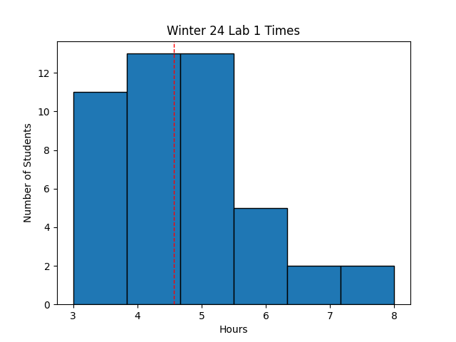 Avg Hours: 4.6, 4.7, 4.8, 3.6 (Winter 2024, 2023, 2022, 2021)
Learning Outcomes
- Understand how to complete and submit lab reports
- Review how to simulate, synthesize, and generate bitstream files from a SystemVerilog file
- Review your SystemVerilog design skills by modifying an existing SystemVerilog file
- Review your understanding of the Vivado design tools by simulating your SystemVerilog module
- Learn how to download your SystemVerilog module onto the Basys3 FPGA board
Preliminary
Each laboratory assignment contains a “Preliminary” section that involves tutorials, training, and reading that will help you get started with the lab before you show up for the lab assignment. You are encouraged to read and start the laboratory preliminary before you show up to the lab. Students who complete the preliminary section of the lab before the laboratory section will be far ahead of other students and have access to the TAs before the TAs get too busy. This preliminary section will guide you through the laboratory completion and submission process and introduce you to the BYU ECEN Digital Laboratory.
Teams Lab Channel
There will be a dedicated channel in the class Teams workspace for each laboratory assignment. You will automatically be added to this channel when it is created. This Teams channel is used to provide updates or clarification on the lab as problems are discovered. Students are encouraged to ask questions about the lab on this channel and provide answers to other students. The TAs and instructor will monitor this channel and provide responses as needed.
What is the preferred way to communicate with the TAs and instructor for laboratory assignments?
Laboratory Completion Instructions
Begin this preliminary by carefully reading through the instructions for completing lab assignments. After reading these instructions, answer each of the following questions in your lab report (i.e., Learning Suite).
What portion of your composite laboratory grade is the “Lab Report” component?
How do you submit a laboratory report in this class?
When are laboratory lab reports due?
Are late lab reports accepted?
How are files submitted for the passoff section of the lab?
When are laboratory Pass Offs due?
Are late lab passoffs accepted?
ECEN Digital Lab
You will use the computers in room 423 EB to access the software for designing digital hardware. To access these computers, you will need an active CAEDM account. Request a CAEDM account if you do not already have one.
When in this room (423 EB), you are required to follow all CAEDM policies. Review these policies and answer the following question:
Which activities are acceptable in the Digital Lab?
Unix
The computers in this lab are configured with Linux and you will be required to navigate the Unix command line to run tools, manage files, and complete laboratory assignments. If you are unfamiliar with Unix, you may want to refer to the ECEN Linux Introduction laboratory to prepare yourself for using Linux. This laboratory includes links to a number of good tutorials for improving your Unix skills. The following ECEN 220 page contains a nice overview of the most common Unix commands you will use in this course.
GitHub
GitHub will be used extensively in this class for submitting and grading your laboratory files.
You will be required to create a GitHub classroom repository to store your laboratory files.
Carefully read and follow the instructions in the GitHub Setup Guide to setup your class repository and import the initial class code.
After completing the instructions in this tutorial and creating your GitHub repository, provide the remote GitHub repository string on Learning Suite.
You can obtain the repository by executing the following command within your repository: git remote get-url origin.
Your response should be in the following form: git@github.com:byu-ecen323-winter2024/323-labs-wirthlin.git (although you will have a different repository name in the same repository classroom).
This string will be used by the grading scripts to clone your repository.
Provide the URL of your class GitHub repository
Note that it is essential that you copy this String correctly. The TA grading scripts will use the string you provide here for extracting your code. You will face a 20% penalty on this lab if this string is entered incorrectly or if the repository is not accessible.
You will need to become familiar with using GitHub for submitting your laboratory files.
To learn some of the most basic functions of Git, complete the GitHub Basic Tutorial.
As part of this tutorial you will create a file named aboutme.txt and commit it to your repository (instructions on what should be included in this file are described in the tutorial).
Make sure the file ‘aboutme.txt’ is committed in the ‘lab01’ directory of your repository.
Note: This green text above indicates that the ‘aboutme.txt’ must be included in your passoff GitHub repository when you submit your lab. This file should contain the information requested during the tutorial and will be reviewed by the TAs.
After reading the instructions on GitHub, answer each of the following questions in your lab report to demonstrate your understanding of Git and its use in the class.
What type of git repository will you be creating for this class?
What git commands should you run to update the starter code in your repository throughout the semester?
Which git commands should you use when submitting your files for the passoff portion of the lab?
Exercises
Exercise #1 - Using the Vivado Design tools
In this course, you will use the Xilinx Vivado design software to design digital circuits and then test those designs on the circuit board.
This software is installed on the lab machines in the EB lab for this class.
It is necessary that you know how to run these tools and become very familiar with these tools.
In this exercise you will learn how to run the Vivado tools in the digital lab and create a simple design to demonstrate your ability to run the tools.
The instructions for setting up your environment for Vivado are described in the ECEN 220 Lab 0 write up under the section titled “Setup Xilinx Design Tool Environment” (Note: the Xilinx setup script has changed to the following path: /tools/Xilinx/Vivado/2023.1/settings64.sh).
You may also access the tools remotely or install them on your own computer. The following page describes Alternative Vivado Tool Use Options. While the use of tools outside of the digital lab are possible, they are not supported by the TAs.
Begin by configuring your environment to access the Vivado tools and run the Vivado tool.
Indicate the version of Vivado that is installed in the digital lab
Your class repository should contain a directory lab01 that contains a number of files that will be used in this exercise.
Make sure you have access to this directory in your local repository as you will need these files to complete several of the lab exercises.
This example includes two SystemVerilog files that define a simple counter circuit that counts the number of times a button has been pressed on the Basys3 board.
In this exercise you will create a project in Vivado using the files in this directory and review the code in this example.
Vivado Projects
The Vivado design tool organizes FPGA designs around the concept of a Vivado ‘project’. A Vivado project includes all of the sources and settings necessary to specify the design, simulate the design, and implement the design on the FPGA. The project also generates a lot of intermediate files during the simulation and implementation process. Each laboratory assignment will involve the creation of one or more Vivado projects for FPGA design. Each Vivado project is given a unique project name and is stored in a specific project directory. One of the challenges in working with Vivado projects is managing the source files used for a project using a Version Control System like GitHub along with all the intermediate files generated in the implementation process.
For this class, you are required to organize your Vivado projects as follows:
- Save all project source files within specific directories within your repository (the specific location will be defined for each lab)
- Name the Vivado project directory “proj” and place this directory as a sub-directory where your project sources are stored. You should not store your source files within the project directory as often happens when you create new files from scratch using the Vivado source editors.
Begin by creating a new project named ‘ButtonCount’ in the lab01/proj_buttoncount directory of your repository.
You can create a new project in two ways.
First, you can create the project using the GUI by following the Creating a Project within Vivado tutorial on the 220 website.
The part that should be specified when creating the project is “xc7a35tcpg236-1”.
Second, you can create a project from the Vivado command line by executing the following tcl commands in the Vivado command line window:
#create_project -force [project name] [project directory]
create_project -force ButtonCount ./proj_buttoncount
# Set the part property for the project to the part on the Basys3 board
set_property "part" "xc7a35tcpg236-1" [get_projects [current_project]]
The TCL commands shown above assume that the current directory in the Vivado command window is the lab01 directory that contains the source files for the project (you can determine the current directory of this shell by using the pwd command on the command line).
You may need to change directories in this window before executing the command using the cd command.
Alternatively, you can change the location of the project window when executing the create_project command.
Once you have created your project, you should change the default settings of several parameters within Vivado.
A script has been created at resources/new_project_settings.tcl in the class repository to make these changes for you.
When in the lab01 directory, run this script as follows to change your default project settings:
source ../resources/new_project_settings.tcl
The ButtonCount design includes two SystemVerilog files: ButtonCount.sv and OneShot.sv (both in the lab01 directory).
The ButtonCount.sv file contains the top-level button counter logic and the OneShot.sv file contains the logic for implementing a simple one-shot pulse detector.
You will need to add both files to the project in order to build the design in the FPGA.
Like creating a project, you can add these files in the project in two different ways.
First, you can add the file using the GUI as described by the ECEN 220 tutuorial.
As an alternative, you can add files to your current project on the Vivado command line using the following tcl command:
add_files ButtonCount.sv OneShot.sv
Note that if the current directory of the Vivado command line window is not lab01 then you will need to change to that directory or specify the path of the ButtonCount.sv file.
It is convenient to create a .tcl file that will do all of these commands for you in a single script. You can add this file to your repository and create a new project without using the GUI. The following example demonstrates the commands you would use to create your project in a single .tcl script:
create_project -force ButtonCount ./proj_buttoncount
set_property "part" "xc7a35tcpg236-1" [get_projects [current_project]]
source ../resources/new_project_settings.tcl
add_files ButtonCount.sv OneShot.sv
After adding the files to your project, open ButtonCount.sv and OneShot.sv in the Vivado text editor to review their contents.
Carefully review the text of these SystemVerilog files to familiarize yourself with the SystemVerilog syntax and the coding style.
The top-level ButtonCount.sv file contains a counter to keep track of the number of button presses and the file OneShot.sv contains the state machine that is used to make sure that the counter is incremented only once each time the button is pressed.
Carefully review the code and find each of these components.
A summary of these components is described below:
ButtonCount.sv
The code in this top-level design includes a 16-bit counter that will increment every time the button is pressed. It also includes a synchronizer to synchronize the button signal to the global clock signal. The counter is reset with a synchronous reset signal (the center button). The output of the counter are tied to the LEDs on the Basys3 board.
What line of code in this file describes the logic used to assign the count value to ‘zero’ when the ‘rst’ signal is asserted?
OneShot.sv
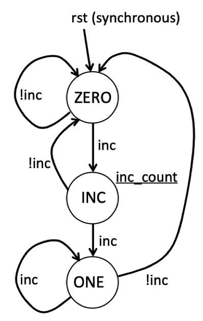
This file includes a state machine that is used to detect the first clock cycle in which the up button transitions from ‘0’ to ‘1’. The reason this state machine is needed is because we do not want to increment the counter for every clock cycle in which the button is pressed. If we did this, the counter would increment too fast for us to see any impact. This state machine keeps track of what the history of the button press has been and then generates an output signal, ‘inc_counter’, that is asserted for only one clock cycle when the button is first pressed. This is sometimes called a “one shot” detector because we want only one clock cycle signal for a long button press.
The state diagram for this state machine is shown below. This state machine has three states: ZERO, INC, and ONE. In the ZERO state, the state machine is waiting for the input signal ‘inc’ to go high. As long as ‘inc’ remains low, the state machine remains in this state. When the input ‘inc’ goes high, the state machine will move to the INC state. During the INC state, the Moore output signal ‘transition’ is high indicating that the input has made a transition from 0 to 1. The state machine will transition from the INC state back to the ZERO state if the ‘in’ signal is zero, otherwise it will move to the ONE state (i.e., when ‘inc’ is 1). The state machine will remain in the ONE state until the ‘inc’ signals returns back to zero. This state machine includes a synchronous reset signal named ‘rst’ that will return the state machine back to the ZERO state on the next positive clock edge.
After reviewing the code for this ButtonCount circuit, determine the values of the ‘inc_count’ signal and the counter value by completing the waveform below.
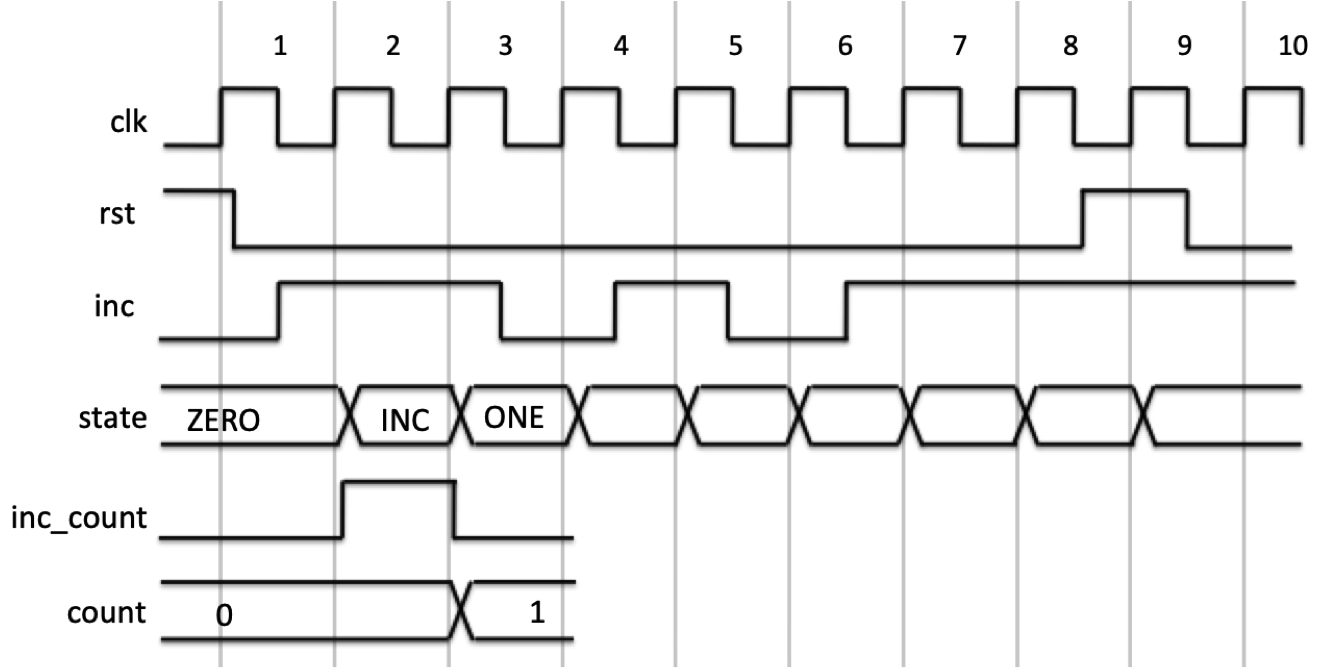
Complete the questions about the waveform in the laboratory report.
Exercise #2 - Vivado Simulation with TCL Scripts
In this next exercise, you will use the Vivado simulator to validate the function of the ButtonCounter circuit. The Vivado simulator will be essential for you to test your circuits throughout the semester and it will be essential for you to learn how to use the Vivado simulator well. Open the Vivado simulator within your project to begin simulation of the circuit. You may want to review the 220 Starting the Vivado Simulation Tools tutorial to help you get started. There are a number of resources that may help you use the simulator:
You can control the simulator using the GUI by clicking various buttons on the simulator tool or by executing “TCL” simulation commands (TCL is a scripting programming language that is often used in design tools like Vivado). You can type the commands by hand or execute TCL simulation scripts that contain a list of TCL simulation commands. For this exercise, you will be simulating your circuit using TCL commands. If you are unfamiliar with using TCL for simulation, you may want to review the 220 TCL 1 and the TCL 2.
A TCL simulation script, ButtonCount_sim.tcl, is included in the local repository to simulate the input waveform provided to you in the previous exercise.
You will need to execute this simulation script within the simulator to simulate the design.
You can execute the script one of two ways:
- Execute the command from the Tcl command line
- Change the current directory of the Tcl Console to the directory:
cd <Path> - Execute the Tcl script:
source ButtonCount_sim.tcl
- Change the current directory of the Tcl Console to the directory:
- Execute the command through the GUI
- Select the menu option: ‘Tools->Run Tcl Script’
- Select the script in the file dialog box
Execute this script and review the waveform output.
Answer the questions in the lab report regarding the results of this simulation waveform output.
Exercise #3 - Synthesis, Implementation, and Bitfile Generation
In this exercise, you will go through the steps required to implement your ButtonCount module and target it for the Basys 3 FPGA board. As you may remember from ECEN 220, there are many steps involved in preparing your SystemVerilog module for the Basys 3 FPGA board. These steps will be summarized below.
Basys 3 FPGA Board
We will be using the Basys 3 FPGA board for many of the laboratory assignments in this class. This is the same board used in the ECEN 220 class so you may already be familiar with its operation, capabilities, and functions. If you are unfamiliar with the Basys 3 board, you can review the features of this board at the following link: Details about the Basys3 board.
The inputs and the outputs of the ButtonCount module need to be connected to specific pins on the FPGA
so that they are hooked up to the proper buttons, leds, etc.
An ‘.xdc’ constraints file is used to map the top-level input/output signals to specific pins on the FPGA. The file ButtonCount.xdc has been created to demonstrate how this is done.
This file uses the following input/output resources on the Basys3 board:
- The global clock input ‘clk’ is connected to the 100 MHz clock
- The ‘rst’ input is connected to the center button (BTNC)
- The counter outputs are connected to the light emitting diodes (LEDs) LD15-LD0 (i.e., count[15], count[14],…,count[0])
You will need to add this file to your project before proceeding with the implementation steps.
You can add the constraints file using the GUI by following this tutorial or you may add it on the command line by executing the following TCL command:
add_files -fileset constrs_1 ButtonCount.xdc
You will need to create/modify an .xdc file in future labs.
The following tutorial describes how to create an .xdc file (although you don’t need to do this for this exercise).
A comprehensive .xdc file has been included in your repository that you can use as the base for your future FPGA designs (see resources/Basys-3_323.xdc).
SystemVerilog Synthesis
The logic synthesis step will take your SystemVerilog code and synthesize a digital circuit from it. The messages generated by the synthesis step are very important and it is essential to review the synthesis logs carefully. The following tutorial describes how to run the synthesis step.
The synthesis step may introduce a number of errors and warnings. These errors must be resolved and the warnings must be understood before proceeding. Carefully review the logs of your synthesis report. Although this SystemVerilog file has been prepared for you and should not have any synthesis errors, you should familiarize yourself with the output of the synthesis command. You may want to refer to the following reference of synthesis warnings to learn about common synthesis warnings you may experience.
Implementation
The next step in the process is to implement the synthesized logic onto the FPGA found on the Basys 3 board. A tutorial describing how to run this tool is provided on the 220 web site. After completing the implementation step, summarize the timing and resource utilization of your design. Details on how to determine the resource utilization and circuit timing can be found at the following tutorial link
Indicate the number of resources consumed by the ButtonCount design in the laboratory report.
Determine the “Worst Negative Slack” or WNS of the ButtonCount circuit.
Bitstream Generation
Finally, create a bitstream of your design by running the generate bitstream tool. Executing the Bitstream Generation Step
Bitstream Download
For the final exercise of this laboratory, download the bitfile onto your Basys 3 board. You will need to download this bitfile onto your own board and make sure it works. The following tutorials may be helpful in this process:
Download the bitstream for your ButtonCount circuit to a Basys 3 board. Make sure the board operates correctly by pressing BTNU to see the LED count increase. Also, press BTNC to reset to make sure the counter resets.
Exercise #4 - Up/Down Button Counter
The final exercise of this lab is for you to create a new SystemVerilog file that performs both ‘up’ counting and ‘down’ counting (i.e., an up/down counter). Close your existing Vivado project and create a new project for this new design.
Copy the ButtonCount.sv file and name it UpDownButtonCount.sv.
Save this file in the lab01 directory and add it to your github repository.
Modify this file to incorporate the following changes:
- Add the additional input ports named “btnd”, “btnl”, and “btnr” for the “Down button”, “Left button”, and “Right button.
- Add a 16-bit input port named “sw” for the 16 switches on the Basys3 board
- Add three more instances of the “One Shot” module to generate a one shot signal for each of the three button inputs (i.e., for “btnd”, “btnl”, and “btnr”).
- Modify the counter logic to operate as follows:
- decrement the counter by 1 every time ‘btnd’ button is pressed.
- increment the counter by the value indicated on the switches every time ‘btnr’ is pressed
- decrement the counter by the value indicated on the switches every time ‘btnl’ is pressed
In this course you are required to follow a coding standard for your SystemVerilog code. A coding standard is used in this course for several reasons. First, having your code written using a clear and consistent standard makes it much easier for the instructor and TA to help you as you debug your logic. Second, code written using a consistent standard is much easier to grade. Third, coding standards are used regularly in industry and it is good to practice using coding standards. Briefly review the coding standard before answering the preliminary questions (there will be several coding standard questions in the preliminary question block). This example follows this coding standard. Also, there is a dedicated web page for SystemVerilog resources you can use to brushen up your understanding of SystemVerilog.
You will need to include the UpDownButtonCount.sv file as part of your “Pass Off” below.
Simulation
Simulate your new file (the compiler may find additional errors when you try to simulate).
Once the simulator has started, copy the .tcl simulation file ButtonCount_sim.tcl that you were given in the previous exercise and name the new .tcl simulation file UpDownButtonCount_sim.tcl.
Save this file in your lab01 directory and add the file to your repository.
Modify this file to simulate both up and down counting
(Note: there is a coding standard for .tcl files - refer to the coding standard guidelines to make sure you code your .tcl file properly).
Include at least three “down” button presses to decrement the counter and at least two more “up” button presses to increment the counter.
You will need to submit the UpDownButtonCount_sim.tcl file as part of your “Pass Off” below.
Implementation
Once you have successfully simulated your new file, you are ready to implement the circuit on the FPGA.
Before proceeding, you will need to create a new .xdc file for your design.
Copy the ButtonCount.xdc file used in the previous exercise and name the new file UpDownButtonCount.xdc (again, in the lab01 directory).
You will need to change this new file by removing the comment (‘#’) on all the lines associated with the three additional buttons and 16 additional switches (two lines per pin).
You will need to include the UpDownButtonCount.xdc file as part of your “Pass Off” below.
After creating your new .xdc file, add it as a constraint file to the project, implement the design and generate a programming bitstream.
Indicate the number of resources consumed by your new design in the laboratory report.
Determine the “Worst Negative Slack” or WNS of this circuit.
Download
Once you have successfully generated a bitstream for your new Up/Down button counter, download this bitstream to your Basys3 board. Experiment with your circuit and verify that (1) you can count up, (2) that you can count down, and (3) that you can reset the counter by pressing the center button. The TAs will generate a bitfile and verify that it works correctly so make sure your circuit works correctly so you get full credit for the lab.
Pass Off
The final step in the laboratory process is to complete the ‘pass off’. Carefully review the instructions for Git Submission as you prepare your submission for this lab. A brief summary of these steps is as follows:
- Update the starter code to make sure you have the latest lab files
- Commit and push your files to the main branch of your remote repository in the
lab01directory. The files that must be committed in this directory are:- UpDownButtonCount.sv
- UpDownButtonCount_sim.tcl
- UpDownButtonCount.xdc
- aboutme.txt
Note: Make sure you do NOT include your Vivado project directory and project files as part of your repository. This directory is very large and will gum up your repository with unnecessary files. You will lose significant points on this lab if you have committed your vivado project directory and project files.
At this point your laboratory pass off is submitted. However, there is a lot that can go wrong with your submission and you should complete the following steps to make sure your submission is valid. Continue with the following steps to verify your submission.
- Prepare the terminal with the Vivado environment
- Run the lab passoff script:
python3 lab01_passoff.py -f
This same script will be run by the TAs so if the script works for you, it will work for the TAs. Check the messages after executing this script to make sure your submission completes successfully. If you have any problems (or warnings for lab 1 specifically) in the execution of this script then you should go back and fix the problem with your code and complete all the submission steps again.
Answer the final two questions in your laboratory report:
How many hours did you work on the lab?
Provide any suggestions for improving this lab in the future