The Vivado logic simulator can also be run in GUI mode to view the “waveforms” of your design.
This form of simulation allows you to more easily see the behavior of your design over time and is often used when debugging logic errors.
This tutorial will describe how you can use the GUI mode of the Vivado simulator to view the waveforms of the example design.
This tutorial will demonstrate this process using the binary_adder.sv design from Lab 2.
Before proceeding with this tutorial, you need to ‘analyze’ and ‘elaborate’ your design as described in the command-line simulation tutorial.
Run Simulation Tool in GUI Mode
To run the simulation in GUI mode, add the -gui flag when running xsim as follows:
% xsim binary_adder -gui --nolog
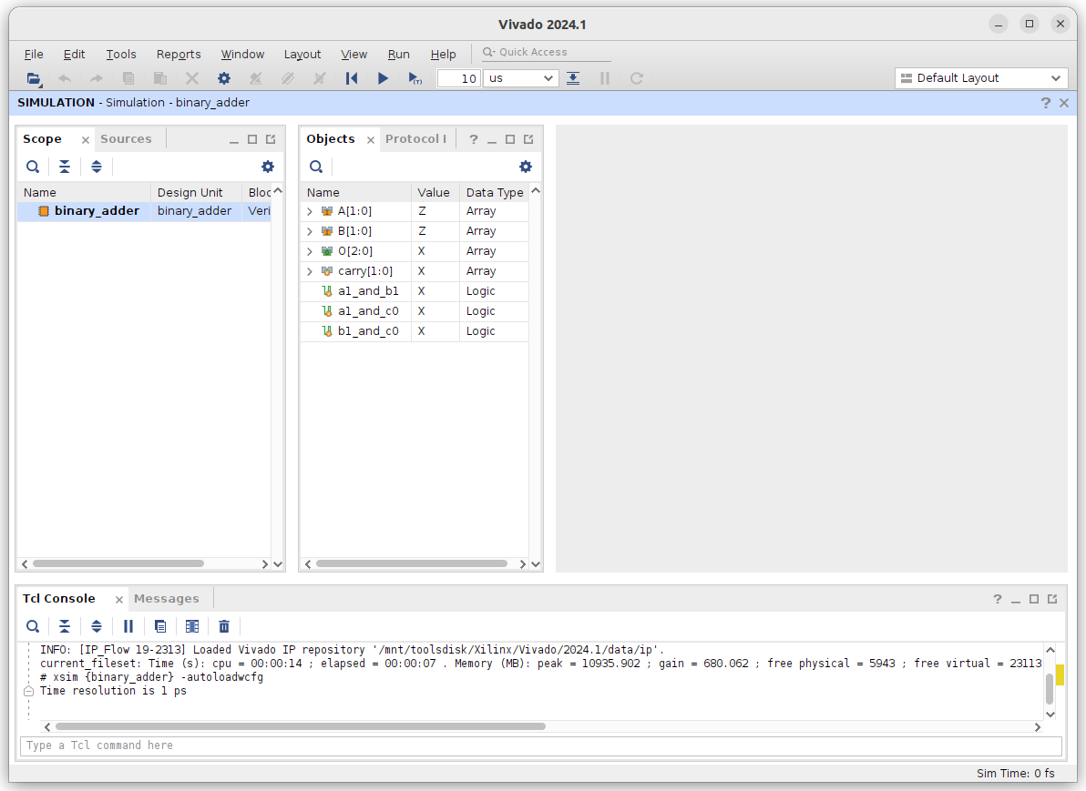
This will open the simulation environment and provide a GUI interface for the simulation. The image below demonstrates what this will look like. This window has several important regions that are described below:
- Tool Bar: At the top is a toolbar with a number of buttons to help with simulation. This will be discussed in more detail below.
- Scope Window: The left side of the window is the scope window. This window shows the hierarchy of your design and allows you to select which signals you want to view.
- Objects Window: The right side of the scope window is the objects window. This window shows the signals that are in the currently selected scope
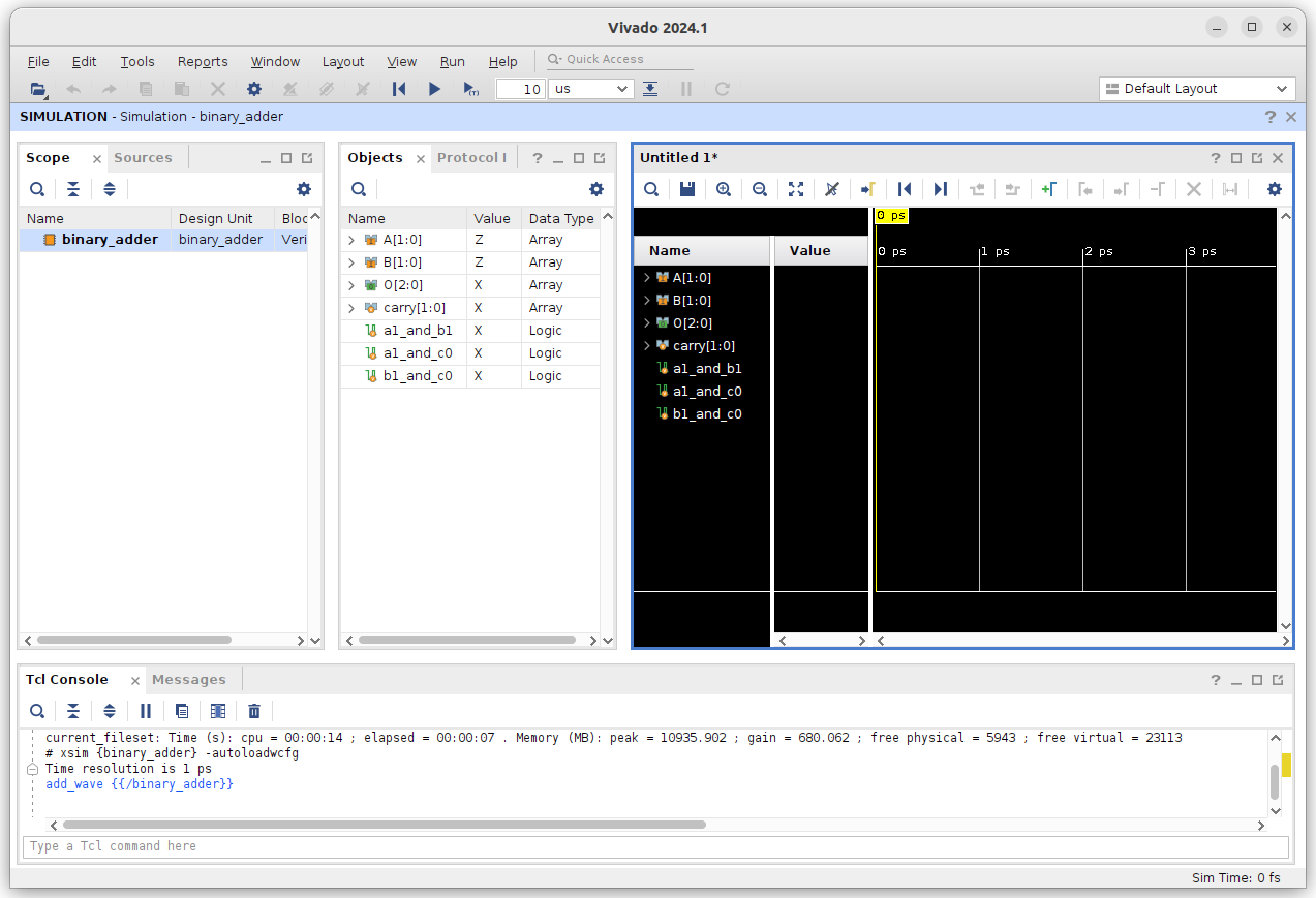
When in GUI mode we are usually interested in viewing the waveforms of the signals in our design. For this example, we will view all the signals in the ‘binary_adder’ module. Select the ‘binary_adder’ in the scope window. Right click and select “Add to Wave Window” to add all the signals in the ‘binary_adder’ module to the waveform viewer. This will create a new waveform window with all the signals of the module shown. The image below shows what this will look like.
At this point you can run the same simulation commands you ran in the command line simulation tutorial.
Commands such as run, set_value, restart, and get_value can be run in the Tcl console at the bottom of the window.
Enter the command run 10 ns to advance the simulation time by 10 ns.
The waveform viewer will update to show the new values of the signals at the new time.
Note that the inputs ‘A’ and ‘B’ are a blue color with the value ‘Z’.
This means that the input signals are undefined.
The other signals are red with a value ‘X’.
This means that the signals are unknown and generally indicates an undesirable simulation value.
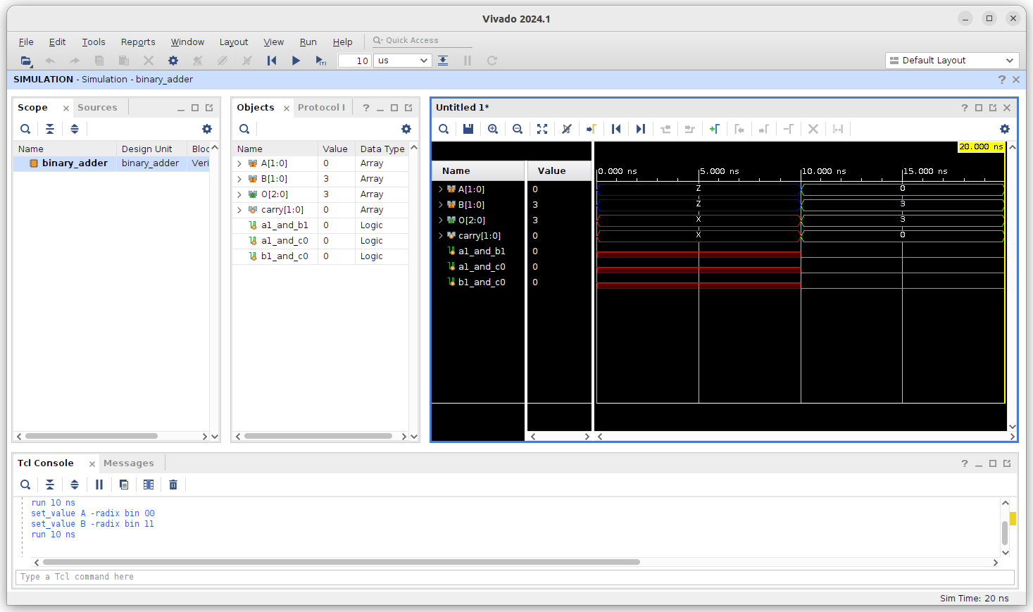
Set a value for both ‘A’ and ‘B’ (using set_value) and advance the simulation by 10 ns (using run) to see the waveform update.
After running the simulation you will see the colors of the waveforms changed.
The waveforms for the switches will now be green with the value you set them to and the waveforms for the other signals (including the LEDs) will be green.
Click the ‘zoom out button’ ![]() in the toolbar to see the entire waveform.
You should see something like the following image:
in the toolbar to see the entire waveform.
You should see something like the following image:
In addition to manually setting values and running the simulator, you can also create Tcl scripts to automate the simulation process. You can also ‘source’ your Tcl script to perform multiple set/run commands like this:
source sim_adder.tcl
When you are done simulating, exit the GUI and click on ‘Discard’ when the dialog box prompts you to save the waveform.
Simulate and Create Waveform with Tcl Script
To automate the simulation process and set up the wave viewer automatically, add the following segment to the very beginning of your Tcl script:
# Check if a waveform configuration is already present
set curr_wave [current_wave_config]
if { [string length $curr_wave] == 0 } {
    # If no waveform configuration exists, create one and add top-level signals
    if { [llength [get_objects]] > 0 } {
        add_wave /
        set_property needs_save false [current_wave_config]
    } else {
        # Warning if no top-level signals are found
        send_msg_id Add_Wave-1 WARNING "No top-level signals found. Simulator will start without a wave window. If you want to open a wave window, go to 'File->New Waveform Configuration' or type 'create_wave_config' in the Tcl console."
    }
}
This will configure the waveform viewer before running the subsequent set_value, run, and other commands in your Tcl file, allowing the wave file to populate and display the signals.
MakeFile for Batch Mode Simulation in GUI
All put together your final makefile command for simulation in the GUI might look something like this:
sim_binary_adder:
    xvlog binary_adder.sv -sv --nolog
    xelab binary_adder -debug typical --nolog
    xsim binary_adder -tclbatch sim.tcl -log sim_adder.log
In all future labs you are allowed and encouraged to copy your MakeFile and Tcl scripts from previous labs to save time, changing the corresponding file, module, and make-command names as needed.