Table of Contents
In the seven-segment decoder laboratory assignment, you created a circuit that can display a hexadecimal value on a single digit.
On this page, you are provided with a Seven-Segment Controller module that can display a unique value on each digit of the four-digit display. Displaying multiple digits on the display is accomplished by multiplexing the cathode signals and “driving” or displaying one digit at a time. To make it appear to the human eye that more than one digit is displayed, we rapidly turn on each digit and sequence through the digits fast enough so the eye and brain cannot see this sequencing. Even though only one digit is actively displayed at a time, our persistence of vision and slow brain response cannot perceive this single digit display strategy. Instead, it will appear as if all four digits are being displayed at the same time. If you were to take a high-speed video of the display and play it back in slow motion, you would see this sequential digit display approach in action.
The example shown below demonstrates how the value “0123” is displayed on the four digits of the display using time multiplexing. In this example, only one digit is being driven on the display at a given time – a “0” is displayed on digit 3 (the left most digit) during the first time period, a “1” is displayed on digit 2 during the second time period, a “2” is displayed on digit 1 during the third time period, and a “3” is displayed on digit 0 (the right most digit) during the fourth time period. This process of displaying one digit at a time repeats continuously to make it appear that all four digits are being displayed at the same time.
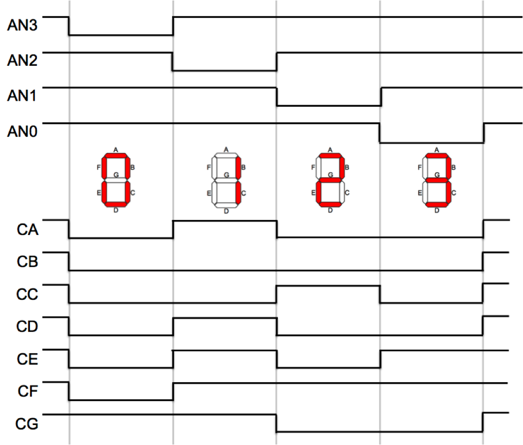
This example demonstrates the signals that must be asserted during each time period to produce the desired display. During the first time period, AN3 is asserted (i.e. is low) and the other anode signals are deasserted. The following cathode signals are asserted (driven low) to display the character “0” on digit 3: CA, CB, CC, CD, CE, and CF. During the next digit period, AN2 is asserted (while AN3 is deasserted) and the following cathode signals are asserted to display the character “1”: CB and CC. Next, AN1 is asserted and the following cathode signals are asserted to display the character “2”: CA, CB, CD, CE, and CG. Finally, AN0 is asserted and the following cathode signals are asserted to display the character “3”: CA, CB, CC, CD, and CG. This process repeats continuously to keep all four values actively highlighted on the four-digit display.
The challenge we have is deciding how long to drive each anode signal. If the “on” time of the anode signals is too long, the eye and brain will detect that only one digit is being displayed at a time and we will see the digits turn on and then off in sequential order. If the “on” time is just right, human brain will perceive all four characters as being displayed at the same time through persistence of vision.
The easiest way to sequence through the four different digits is to create a “free running” counter. A free running counter is a counter that increments continuously at each clock cycle (See Figure 16.6). When the free running counter reaches all 1’s, it will then roll over to zero on the next clock cycle. The top two bits of this free running counter will cycle through the digits, while the rest of the bits of the counter will determine the amount of time to display each digit. For example, suppose you used a 7-bit counter. Then, the top two bits of the counter would determine which digit to display and the bottom 5 bits would be used to count the duration that each digit is displayed. With 5 bits, each digit will be displayed for 25 = 32 clock cycles.
The table below summarizes how the top two bits of this free running counter are used to select the appropriate digit in the display:
| Top 2 Bits | Function |
|---|---|
| 00 | Display digit 0 (right most) - Assert AN0 |
| 01 | Display digit 1 - Assert AN1 |
| 10 | Display digit 2 - Assert AN2 |
| 11 | Display digit 3 (left most) - Assert AN3 |
The clock we have on the Basys 3 board runs at 100 MHz with a clock period of 10 ns. If you use a seven-bit counter to sequence the digits as described above, the top two bits would be used to sequence through each digit and the bottom five bits would be used to count the number of clock cycles to display each digit. Thus, each digit would be displayed for 25 x 10 ns = 320 ns. (The module provided below does not use a 7-bit counter, this is just described here as an example).
The counter in the module given to you is not fixed in width at 7-bits, but rather is parameterizable through the “parameter” keyword. Look at the SystemVerilog file below to see the default width of the counter.
SystemVerilog Module
Here is the SystemVerilog module. To use this in your Vivado project, 1) click the link to download the file directly, 2) move the file to your project directory, and 3) add the file as a source in your Vivado project.
//////////////////////////////////////////////////////////////////////////////////
//
//  Filename: SevenSegmentControl.sv
//
//  Author: Mike Wirthlin, Jeff Goeders
//
//  Description: Four-Digit Seven-Segment Controller
//
//
//////////////////////////////////////////////////////////////////////////////////
`default_nettype none

module SevenSegmentControl (
    input wire logic            clk,
    input wire logic            reset,
    input wire logic    [15:0]  dataIn,
    input wire logic    [3:0]   digitDisplay,
    input wire logic    [3:0]   digitPoint,
    output logic        [3:0]   anode,
    output logic        [7:0]   segment
    );

    parameter integer COUNT_BITS = 17;

    logic   [COUNT_BITS-1:0]    count_val;
    logic   [1:0]               anode_select;
    logic   [3:0]               cur_anode;
    logic   [3:0]               cur_data_in;

    // Create counter
    always_ff @(posedge clk) begin
        if (reset)
            count_val <= 0;
        else
            count_val <= count_val + 1;
    end

    // Signal to indicate which anode we are driving
    assign anode_select = count_val[COUNT_BITS-1:COUNT_BITS-2];

    // current anode
    assign cur_anode =
        (anode_select == 2'b00) ? 4'b1110 :
        (anode_select == 2'b01) ? 4'b1101 :
        (anode_select == 2'b10) ? 4'b1011 :
        4'b0111 ;

    // Mask anode values that are not enabled with digit display
    // (if a bit of digitDisplay is '0' (off), then it will be
    // inverted and "ored" with the anode making it '1' (no drive)
    assign anode = cur_anode | (~digitDisplay);

    // This is a statement to simulate a common student problem when the
    // anode is "stuck". This statement is used to make sure the testbench
    // catches this condition.
    //assign anode = 8'hff;

    assign cur_data_in =
        (anode_select == 2'b00) ? dataIn[3:0] :
        (anode_select == 2'b01) ? dataIn[7:4] :
        (anode_select == 2'b10) ? dataIn[11:8]:
        dataIn[15:12] ;

    // Digit point (drive segment with inverted version of digit-point input)
    assign segment[7] =
        (anode_select == 2'b00) ? ~digitPoint[0] :
        (anode_select == 2'b01) ? ~digitPoint[1] :
        (anode_select == 2'b10) ? ~digitPoint[2] :
        ~digitPoint[3] ;

    assign segment[6:0] =
        (cur_data_in ==  0) ? 7'b1000000 :
        (cur_data_in ==  1) ? 7'b1111001 :
        (cur_data_in ==  2) ? 7'b0100100 :
        (cur_data_in ==  3) ? 7'b0110000 :
        (cur_data_in ==  4) ? 7'b0011001 :
        (cur_data_in ==  5) ? 7'b0010010 :
        (cur_data_in ==  6) ? 7'b0000010 :
        (cur_data_in ==  7) ? 7'b1111000 :
        (cur_data_in ==  8) ? 7'b0000000 :
        (cur_data_in ==  9) ? 7'b0010000 :
        (cur_data_in == 10) ? 7'b0001000 :
        (cur_data_in == 11) ? 7'b0000011 :
        (cur_data_in == 12) ? 7'b1000110 :
        (cur_data_in == 13) ? 7'b0100001 :
        (cur_data_in == 14) ? 7'b0000110 :
        7'b0001110 ;

endmodule
Module Description
The controller has the following three important inputs:
- “dataIn” (16 bits): Each digit can display 4-bits of data. With four digits, the seven-segment display can display up to 16-bits of data. You provide a 16-bit data input that indicates what data to display on all 4 of the digits.
- “digitDisplay” (4 bits): The seven-segment controller does not need to turn on all four digits of the display all of the time. In some applications, you may only want to display two of the four digits (when there is only 8-bits of data to display). The controller can “turn off” or disable individual digits of the display by never asserting their corresponding anode signals. This digit display input will have one bit for each digit of the display. A ‘1’ in this bit indicates that the controller should turn on the digit, while a ‘0’ turns off the digit. For example, if you always want all digits to be turned on, you can connect 4’b1111 to the “digitDisplay” port.
- “digitPoint” (4 bits): There is one digit point in the bottom right corner of each digit of the seven-segment display and there is a corresponding cathode signal for this digit point. This 4-bit input indicates which of the digit points of the display you are to highlight. There is one bit for each of the digits in the display. A ‘1’ indicates that the corresponding digit point should be turned on and a ‘0’ indicates that the corresponding digit point should be turned off. For example, if you only want the leftmost digit point lit up, you can connect 4’b1000 to the “digitPoint” port.
Full list of ports for this module:
| Module Name: SevenSegmentControl | |||
|---|---|---|---|
| Port Name | Direction | Width | Function |
| clk | Input | 1 | 100 MHz System Clock |
| reset | Input | 1 | Active high reset, which resets the counter |
| dataIn | Input | 16 | Data value to display |
| digitDisplay | Input | 4 | Indicates which digits to display |
| digitPoint | Input | 4 | Indicates which digit points to turn on |
| anode | Output | 4 | Anode signal for each of the 8 digits |
| segment | Output | 8 | Segment signals ([7] is digit point, [6:0] are regular segments) |