Table of Contents
The purpose of this lab is to design a code breaker circuit that will decrypt a secret message by identifying the correct key. You will create a state machine to search for the correct key and display the decrypted message on the VGA display.
Learning Outcomes
- Implement a state machine using behavioral SystemVerilog
- Interact with previously designed modules
Preliminary
This lab involves encryption and decryption of messages using digital hardware. At the most basic level, an encryption process takes two inputs: a message (we call plaintext) and a secret key (we call the key). It produces an encrypted message, called the ciphertext. Decryption is the reverse process. It takes the ciphertext and the same original key, and produces the original plaintext.
In this lab we will be using the RC4 encryption algorithm. It’s an old encryption algorithm that is no longer considered secure, but it is useful for simple encryption tasks like this lab. For our system, we are going to use messages that are 16 bytes long (128 bits), and a 24 bit key.
How many different key values can our system have?
Assuming that valid messages are represented as ASCII characters A-Z, 0-9 and space, how many possible valid messages can be represented?
As an example, we may have a 16 byte message, “WE LOVE ECEN 320”, which we can assign to logic in SystemVerilog like this:
logic [127:0] plaintext;
assign plaintext = {8'h57, 8'h45, 8'h20, 8'h4C, 8'h4F, 8'h56, 8'h45, 8'h20, 8'h45, 8'h43, 8'h45, 8'h4E, 8'h20, 8'h33, 8'h32, 8'h30};
// The above is split up to show the individual bytes, we could also store it like this:
assign plaintext = 128'h5745204C4F5645204543454E20333230;
// Or like this:
assign plaintext = {"W", "E", " ", "L", "O", "V", "E", " ", "E", "C", "E", "N", " ", "3", "2", "0"};
// Or like this:
assign plaintext = {"WE LOVE ECEN 320"};
// All of the above assign the plaintext to an identical value
If we encrypt this message using the following key:
logic [23:0] key;
assign key = 24'h010203;
then the resulting ciphertext will be equal to 128'h5c057e9fd5458ec36d7ef9cc4d22ea3e.
If you look up these values in the ASCII table, you will see that the ciphertext is not a readable message.
For example, the first byte, 5c is for character \, and some of the bytes (such as ea) aren’t even valid ASCII character values.
If we decrypt this ciphertext with the same key, we will get back the original message.
If we use the wrong key, we will get another unreadable message.
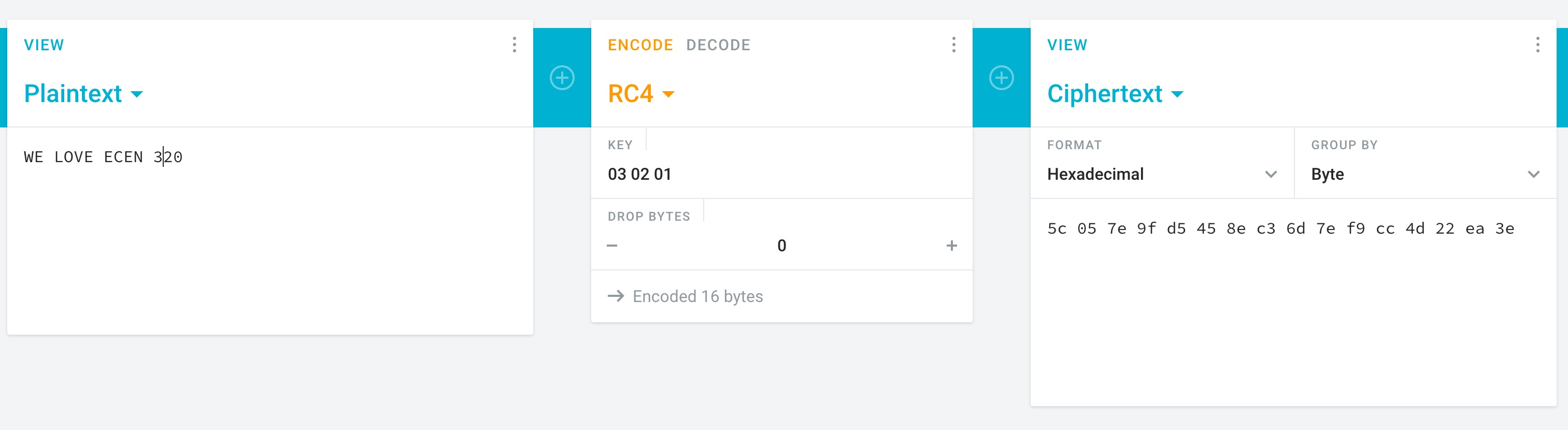
If you’re interested, you can try this out on https://cryptii.com/pipes/rc4-encryption.
Just keep in mind you need to reverse the bytes of the key.
If you choose key = 24'h010203, then enter 03 02 01 for the key on the website.
The following image demonstrates how to use the website to encrypt and decrypt a message.
Answer the following questions using the website listed above.
Assuming the key is 24’h3fe21b, determine the encrypted value of the message ‘WE LOVE ECEN 320’. Paste the encrypted text directly from the web page (including spaces).
Using the same key shown above, decrypt the following message:0f 84 4e 5b 0b 4e 42 d3 5d 06 3c 6a 1a 5a 15 24. Make sure your response is 16 ASCII characters.
Assuming the key is 24’h3fe21X, where the last four bits of the key are unknown (represented by the ‘X’). Determine the key value that will decrypt the message ‘35 6b 6b a4 dd 97 71 20 f3 46 3c c9 09 4b 97 26’. Provide the key value as a 4-bit binary number. You will need to manually try mulitple values until you find a key that produces legible ASCII data.
Top-Level Design
To implement this system, you will create the following top-level design:
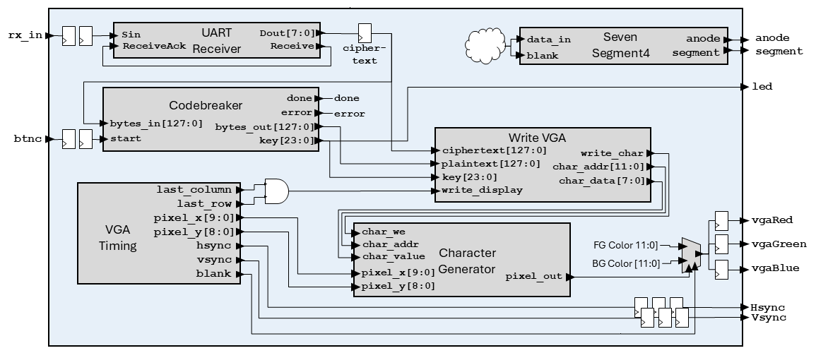
Note: The above diagram does not show every element of the design, certain items are omitted for clarity (e.g., clocks, resets, seven segment logic).
Some notable items in the design include:
- When the UART receiver receives a byte, it shifts it into the lowest byte of the
ciphertextregister. All other bytes in theciphertextregister are shifted up by one byte. This way, you can load theciphertextregister with a new message by sending 16 bytes over the UART. - The
ciphertextis input to the codebreaker module, which searches for a working key when thebtncbutton is pressed. - The VGA timing module and character generator module are configured like last lab. The VGA colors will pull from the foreground and background colors based on
pixel_out. However, unlike last lab, the colors will be fixed (i.e. cannot be changed with the buttons/switches). - A module will be provided, Write VGA, that will write the current plaintext, ciphertext, and key to the character generator. You can use the
last_rowandlast_columnsignals to make this happen at the end of each frame. This will allow you to watch the key search in real time like this:
Exercises
Before starting, make sure to merge in any changes from the startercode. Go to the Submission Instructions page and follow step 1.
Exercise #1: Decrypt Module
To help you with this lab, a RC4 decryption module has been provided for you (see decrypt_rc4/decrypt_rc4.sv in the startercode).
This module performs RC4 decryption/encryption on a 128-bit message and a 24-bit key.
Because you will be instancing this module in your lab as part of the codebreaker assignment, it is important that you understand how the module operates.
Assuming one is using the provided module to perform RC4 decryption, the ciphertext is provided to the bytes_in input, and the key to the key input.
The decryption process begins when the enable signal is raised, and when completed, the done output will be high for a single cycle (unlike the rx module you created, there is no handshake, so the parent module must always be watching the done signal).
The resulting plaintext is available from the bytes_out output, which won’t change until you start a new encryption/decryption process (by lowering and raising the enable signal).
Review the source of the decrypt_rc4.sv file and answer the following questions:
How many bits is the bytes_in port when using default parameters?
How many bits are in the dual_port_ram memory used by the module?
How many write ports are there in the memory used by the module?
How many states are used in the state machine?
Simulate the decrypt_rc4 module performing decryption on two ciphertext/key pairs.
Organize your tcl file as follows:
- Start with the
restartcommand - Create an oscillating clock signal with a period of 10ns
- Set the reset to
1 - Set default values for the signals and run for a few clock cycles
- Run the decrypt function by setting enable to
1with the following inputs:key=24'h010203ciphertext=128'h5745204C4F5645204543454E20333230
- Run for 11 us (the decryption should be done by this time)
- Set
enableto0and run for 1 us - Run the decrypt function by setting
enableto1with the following inputs:key=24'h3fe21bciphertext=128'h0f844e5b0b4e42d35d063c6a1a5a1524
- Run for 11 us (the decryption should be done by this time)
- Set
enableto0and run for 1 us
Note than when writing your .tcl scripts you can specify constants using the -radix flag as follows:
add_force bytes_in -radix hex 5745204C4F5645204543454E20333230
In your simulator window, you may want to change the radix of the bytes_in and bytes_out signals to ASCII so that you can easily see the plaintext and ciphertext messages.
Make sure the results from your decryption/encryption are correct (see your responses to the preliminary to check your results). After simulating the decryption process successfully, take a screenshot of the full simulation.
Include the file decrypt_rc4/sim.tcl in your repository.
Include the file decrypt_rc4/sim.png in your repository.
Exercise #2: Codebreaker Module
For this exercise you will create a module in codebreaker/codebreaker.sv that performs the primary code breaking function of this lab.
This module will perform a brute-force search by performing the decrypt function multiple times with all possible keys to determine the key used to encrypt the message.
Once a valid plain text message is received (i.e., all characters are A-Z, 0-9, [space]), the module will stop and provide the key needed to decrypt the message and the resulting plain text.
You might be worried that you will find a key that produces a readable message, but it is not the correct key.
Don’t worry, the odds of this are about 1 in 1.6 million (and we’ve double-checked that this won’t happen with the encrypted messages you will be tested with).
Begin this exercise by creating a module with the following ports:
| Module Name: codebreaker | ||
|---|---|---|
| Parameter | Default | Function |
| MAX_KEY | 24'hffffff |
Maximum key value to check (i.e., the largest possible key). It will take too long to simulate all 24-bit keys, so this parameter is used by the testbench to limit the search space and verify the error output is working correctly. |
| Port Name | Direction | Width | Description |
|---|---|---|---|
| clk | Input | 1 | 100 MHz Clock |
| reset | Input | 1 | Active-high reset |
| start | Input | 1 | Set high to start running the codebreaker |
| done | Output | 1 | High when the key search completes (on success or error). Stays high until reset or starting a new search |
| error | Output | 1 | Indicates the previous codebreak resulted in no match. Stays high until reset or starting a new search |
| key | Output | 24 | Encryption key |
| bytes_in | Input | 128 | Input bytes (cipher text) |
| bytes_out | Output | 128 | Output bytes (plain text) |
Follow the steps below to build your codebreaker module.
decrypt_rc4
Begin this module by instancing the decrypt_rc4 module in your codebreaker module and connecting the clk, reset, key, and bytes_out ports.
Add internal signals for the other ports.
The instructions below will describe how these other ports are to be used.
ASCII Message Check
An important function that your module must perform is to determine whether the decrypted message is a valid ASCII message (i.e., the message in the bytes_out output of the decrypt_rc4 module).
Once you determine that the decrypted message is a valid ASCII message, you can stop the searching for a key.
To determine if the decrypted message is a valid ASCII message, you will need to check each byte of the message to make sure it is a valid ASCII character. The following function can be added to your module to determine if a byte is a valid ASCII character (in this case we are only accepting capital letters, numbers, and spaces).
// Determines whether the input byte is an ASCII character
function logic isAscii(input logic [7:0] byte_in);
    isAscii = ((byte_in >= "A" && byte_in <= "Z") ||
            (byte_in >= "0" && byte_in <= "9") ||
            (byte_in == " "));
endfunction
You can then use this function to create a logic expression that checks all the 16 bytes of the message simultaneously to determine if all bytes are ascii.
assign is_ascii = isAscii(bytes_out[127:120]) && isAscii(bytes_out[119:112]) &&
                  isAscii(bytes_out[111:104]) && isAscii(bytes_out[103:96]) &&
                  isAscii(bytes_out[95:88]) && isAscii(bytes_out[87:80]) &&
                  isAscii(bytes_out[79:72]) && isAscii(bytes_out[71:64]) &&
                  isAscii(bytes_out[63:56]) && isAscii(bytes_out[55:48]) &&
                  isAscii(bytes_out[47:40]) && isAscii(bytes_out[39:32]) &&
                  isAscii(bytes_out[31:24]) && isAscii(bytes_out[23:16]) &&
                  isAscii(bytes_out[15:8]) && isAscii(bytes_out[7:0]);
Ciphertext and Key Register
You will need a 128-bit register to store the original ciphertext provided.
The ciphertext register should be loaded with the value of the bytes_in input when a new code breaking operation is started (i.e., when the start signal is asserted and you are in an IDLE state).
The ciphertext register will remain the same during the full duration of the code breaking operation.
It’s good practice to save the input in a register so that you don’t rely on the input staying stable during the entire code breaking process (which could take a long time).
The key output should be a register that is initialized to zero when the code breaking operation starts, and incremented by one each time a new decryption operation is started.
This is described in the state machine section below.
State Machine
You will need a state machine to control the operation of the codebreaker. This state machine is designed to continuously perform the decryption operation with incrementing key values until a valid ASCII message is found. A flow diagram of the state machine is shown below:
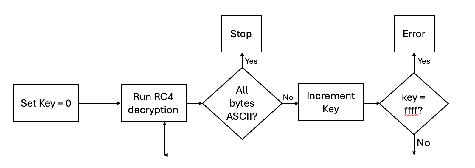
In particular, your state machine should:
- When
startis asserted, initialize thekeyregister to 0 and theciphertextregister to the input ciphertext. Thebytes_ininput will only provide the ciphertext at the beginning of the operation, make sure to save it as described, or it won’t work correctly. - Start a decrypt operation with the current key.
- When the decrypt is over, check to see if the message is all ASCII. If so, exit and raise the
doneoutput (this is thedoneoutput of thecodebreakermodule, which is different than thedoneoutput of thedecrypt_rc4module). Wait until thestartsignal goes low before accepting a newstartsignal. - If the message is not ASCII, increment the key and try decrypting again.
- If you have tried all possible keys (i.e., the
keyisMAX_KEY, and you haven’t found a match), then exit operation, assert thedoneoutput and theerroroutput.
Include the file codebreaker/codebreaker.sv in your repository.
Exercise #3: Testbench
A testbench has been created for you to test your codebreaker module. Make sure that your testbench simulates without any errors.
Exercise #4: Top-Level
For this exercise you will create a top-level module codebreaker_top/codebreaker_top.sv as described in the preliminary above.
| Module Name: codebreaker_top | ||
|---|---|---|
| Parameter | Default | Function |
| FILENAME | ”” | Specifies the filename of the initial contents of character memory |
| CLK_FREQUENCY | 100_000_000 | Specifies the frequency of the clock in Hz |
| BAUD_RATE | 19_200 | Determine the baud rate of the receiver |
| WAIT_TIME_US | 5_000 | Determines the wait time, in micro seconds, for the debounce circuit |
| REFRESH_RATE | 200 | Specifies the display refresh rate in Hz |
| FOREGROUND_COLOR | 12’hfff | Specifies the default foreground color |
| BACKGROUND_COLOR | 12’h000 | Specifies the default background color |
| Port Name | Direction | Width | Function |
|---|---|---|---|
| clk | Input | 1 | 100MHz System Clock |
| btnd | Input | 1 | Reset |
| btnc | Input | 1 | Start codebreaker |
| rx_in | Input | 1 | UART Receiver Input |
| led | Output | 16 | Display upper 16 bits of key |
| Hsync | Output | 1 | Horizontal synchronization signal |
| Vsync | Output | 1 | Vertical synchronization signal |
| vgaRed | Output | 4 | Red color signal |
| vgaGreen | Output | 4 | Green color signal |
| vgaBlue | Output | 4 | Blue color signal |
| anode | Output | 4 | Anode signals for each of the four display digits |
| segment | Output | 8 | Cathode signals for seven-segment display |
- UART Receiver: Connect the UART receive in a similar manner to last lab.
- 128-bit
ciphertextregister:- This should be a byte-wise shift register that shifts in the data from the UART whenever a new byte is received. Feed the data into the lowest byte of the register and shift the remaining bytes up by one byte (i.e.,
ciphertext <= {ciphertext[119:0], Dout}) - This register should be initialized to the value
128'h7d1fd1e0e0b4eeeba6d6d91e2c05d5cbin the signal declaration, and when theresetsignal is asserted. Note: although initializing signals at declaration is generally prohibited (see coding standard rule S12), this lab explicitly allows initializing ciphertext at signal declaration as described above.
- This should be a byte-wise shift register that shifts in the data from the UART whenever a new byte is received. Feed the data into the lowest byte of the register and shift the remaining bytes up by one byte (i.e.,
- Instance the
codebreakermodule as shown in the diagram.- Make sure the upper 16 bits of the current key are displayed on the LEDs.
- Instance the VGA timing, character generator, and write VGA modules as shown in the diagram. The
write_vgamodule is provided for you. - Connect up the VGA outputs in a similar manner to last lab, except that the foreground and background colors are now fixed parameters, not registers.
- Instance the seven-segment module.
- When the codebreaker is running (i.e., when the
donesignal is low), blank the seven-segment display. - When the codebreaker is done, display
C0DEif a key was found, andDEADif no key was found.
- When the codebreaker is running (i.e., when the
- You should use the
FILENAMEparameter to preload the character generator with a provided template that matches the video shown above.- The file
background_template.txthas been provided to you as a template. Copy this file, rename it tobackground.txt, and modify it to include your NetID. - Create a Makefile rule named
background.memthat will generate a memory file namedbackground.memfrom your background file using the python script from the previous lab.
- The file
Include the file codebreaker_top/background.txt in your repository.
Include the file codebreaker_top/codebreaker_top.sv in your repository.
Exercise #5: Top-Level Simulation
After completing your top-level module, simulation your top-level module with a tcl script. Follow these guidelines when creating your tcl file and simulating the top-level:
- Set the following parameters:
SIM_PARAMS = WAIT_TIME_US=50 FILENAME=../../background.memThis will specify the background file to use for the VGA display so you can see values being displayed in your simulation.
- Generate a free running clock
- Set default values for all top-level inputs (make sure
rx_inis1) - Issue a reset by asserting
btnd - Set
btnchigh for at least 50 us to start the codebreaker - Simulate the receiving of a character over the
rxmodule (consider copying tcl code from your lab 11 tcl file) - Simulate for at least one full frame (16.7 ms) so you can see the
write_vgamodule write to the character generator
After creating your tcl file, simulate your top-level module and take the following screenshots:
- A screenshot of your ciphertext register being updated after the
rxmodule receives a byte. This screenshot should include therx_insignal and theciphertextregister so that you can clearly see the ciphertext register update. Name this screenshotsim.png - A screenshot of the
write_vgamodule performing writes to the character generator at the end of the frame. This screenshot should include thechar_addr,char_data, andwrite_charsignals so you can see the data being written to the character memory. Name this screenshotsim2.png
Include the file codebreaker_top/sim.tcl in your repository.
Include the file codebreaker_top/sim.png in your repository.
Include the file codebreaker_top/sim2.png in your repository.
Exercise #6: Synthesis and Implementation
-
Create a
codebreaker_top/basys3.xdcfile that contains pin location definitions for each of your I/O ports.Include the file
codebreaker_top/basys3.xdcin your repository. - Set the synthesis parameters:
SYNTH_PARAMS = FILENAME=../../background.mem -
Run synthesis and review the synthesis log for warnings. Note that you will likely see warnings about the
decrypt_rc4module not being fully covered in a case statement “Synth 8-155”. This is ok for always_ff blocks and can be safely ignored. - Run implementation.
Exercise #7: Download and Test
Download your bitfile and test your codebreaker on the Basys3 board by pressing btnc.
Make sure that the LED/seven segment display is displaying the key being tested and that the VGA is showing the correct output.
A python script send_cipher.py has been created to send a variety of ciphertext messages to your Basys3 board.
The python script includes five encrypted messages and one incomplete message that you can use to test your codebreaker.
Run this script and select a ciphertext message (0-6) to send to your Basys3 board.
Note that ciphertext message 0 is the same as the default ciphertext loaded into the ciphertext register.
python3 send_cipher.py --port /dev/ttyUSB1
For each message, determine the 16-byte plaintext message and the corresponding key.
What is the plain text and key for message #0?
What is the plain text and key for message #1?
What is the plain text and key for message #2?
What is the plain text and key for message #3?
What is the plain text and key for message #4?
Message 5 is an invalid message that does not have an ASCII plaintext.
Load this message and make sure you get the error DEAD when the search completes.
Final Pass-Off
Refer to the passoff tutorial for the passoff process.
- See
required_filesin the passoff script. - Makefile rules that must work correctly and be free from errors and warnings:
Makefile:clean,background.memcodebreaker/Makefile:sim_tbcodebreaker_top/Makefile:synth,implement
Answer the final two questions in your laboratory report:
How many hours did you work on the lab?
Provide any suggestions for improving this lab in the future