You previously used the make pre_synth_schematic command to view the schematic of your design before synthesis.
When you used this previously, you were using a design that was “flat”, meaning that it did not contain any hierarchy between modules.
However, in most designs, you will have a hierarchy of modules that are connected together to form a larger design.
This tutorial will show you how to navigate the hierarchy of modules in the Vivado schematic viewer.
This tutorial is based on the top-level design used in the Arithmetic Lab.
Begin by opening your design in the schematic viewer:
make pre_synth_schematic
You should see a schematic that looks similar to the one shown below:
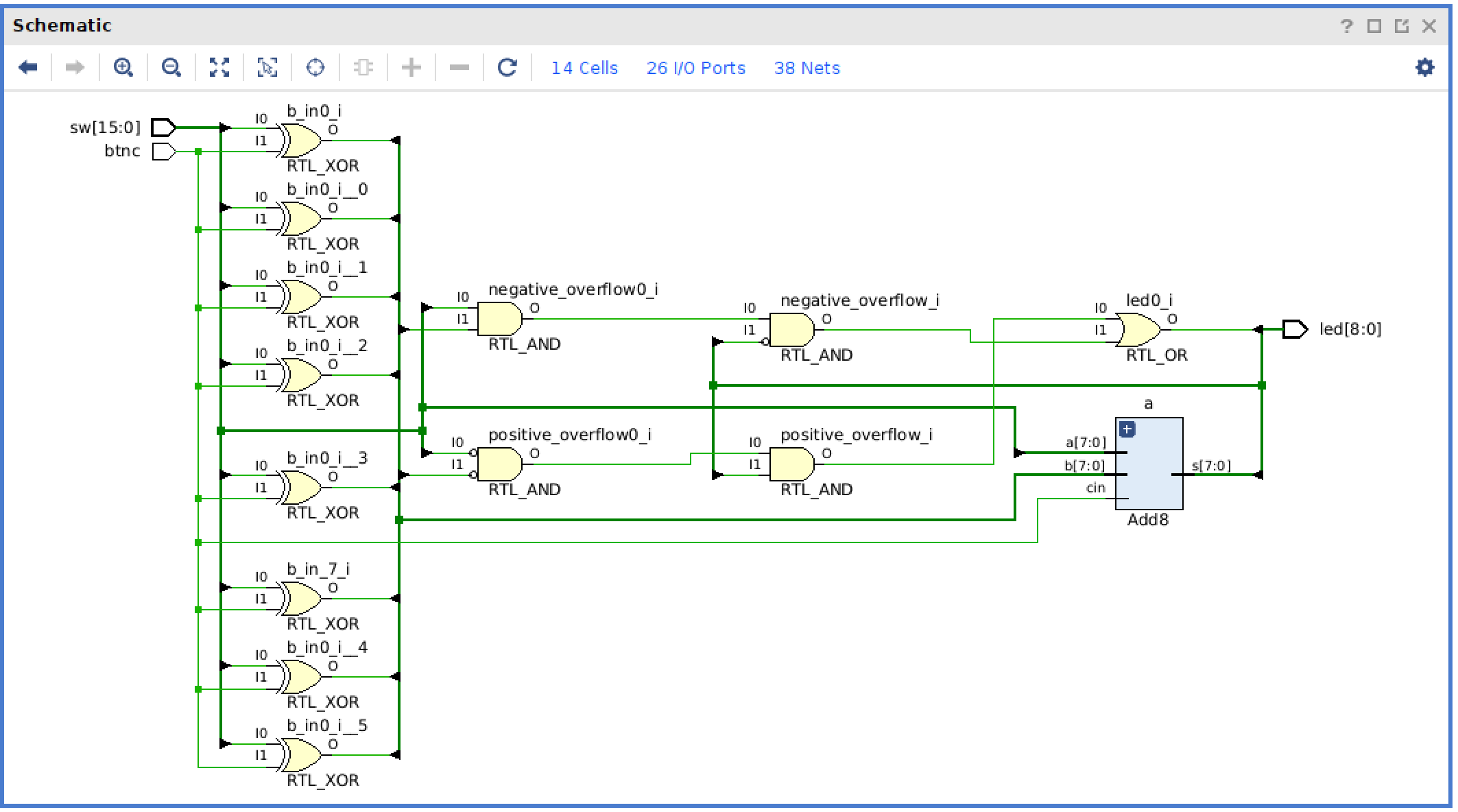
This schematic is very similar to the schematic you have seen in previous labs with gates and wires.
One difference is that you will see a blue box with the name add_8.
This blue box represents the add_8 module that exists within the top-level design.
At this current level, you are viewing the top-level gates connected to the inputs/outputs of the instantiated add_8 module.
Double-click on the add_8 module to view the schematic at the add_8 level of hierarchy.
You should see a schematic that looks similar to the one shown below.
This schematic shows the eight full_add modules that make up the add_8 module.
You are viewing a “lower” level of hierarchy than the top-level design.
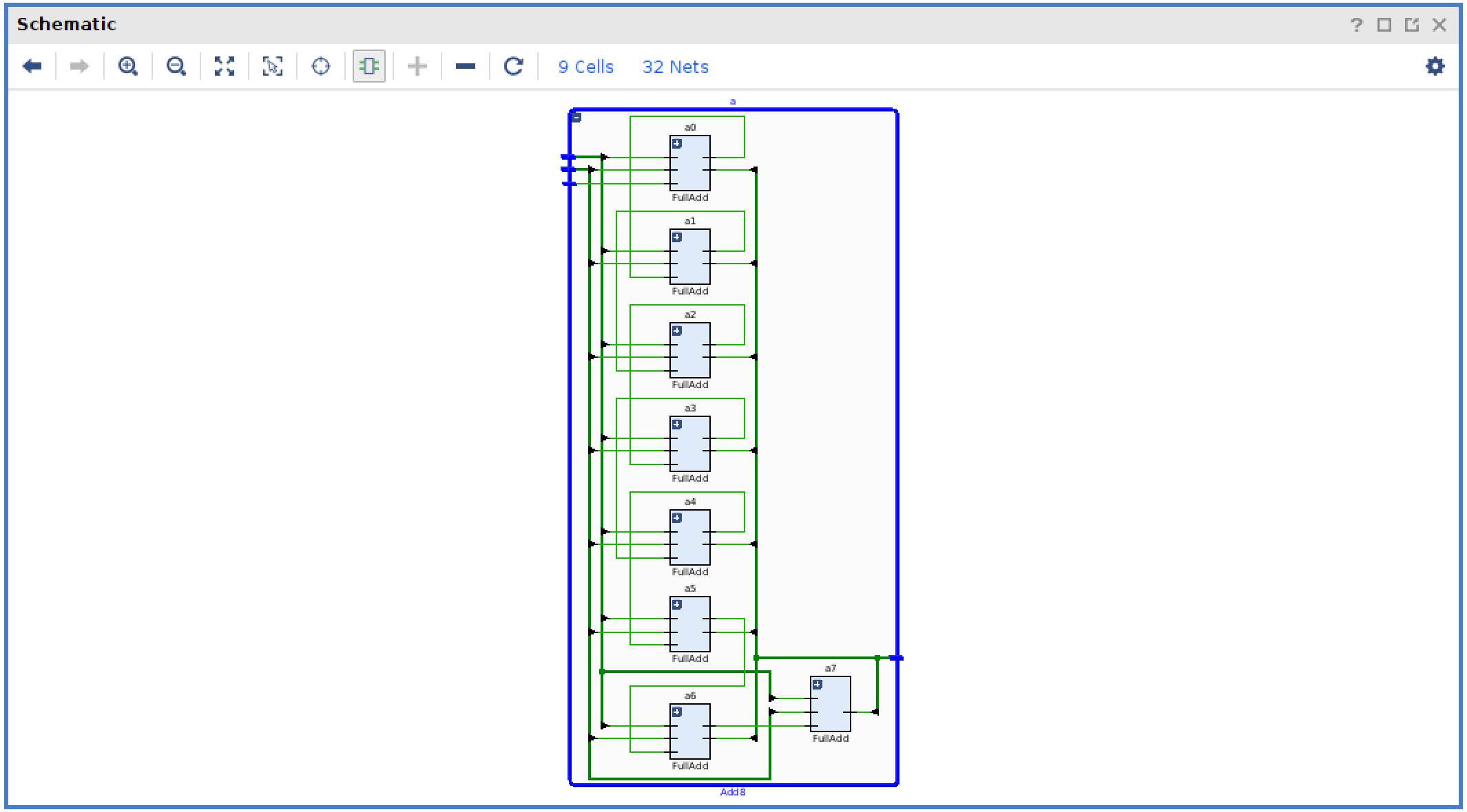
You can go back up a level in hierarchy by pressing the left arrow icon.
Notice the ‘+’ on each of the full_add instances in your add_8 module.
Pressing the ‘+’ will cause the schematic viewer to show the internal contents of the full_add module within the context of the add_8 module.
The image below demonstrates this concept.
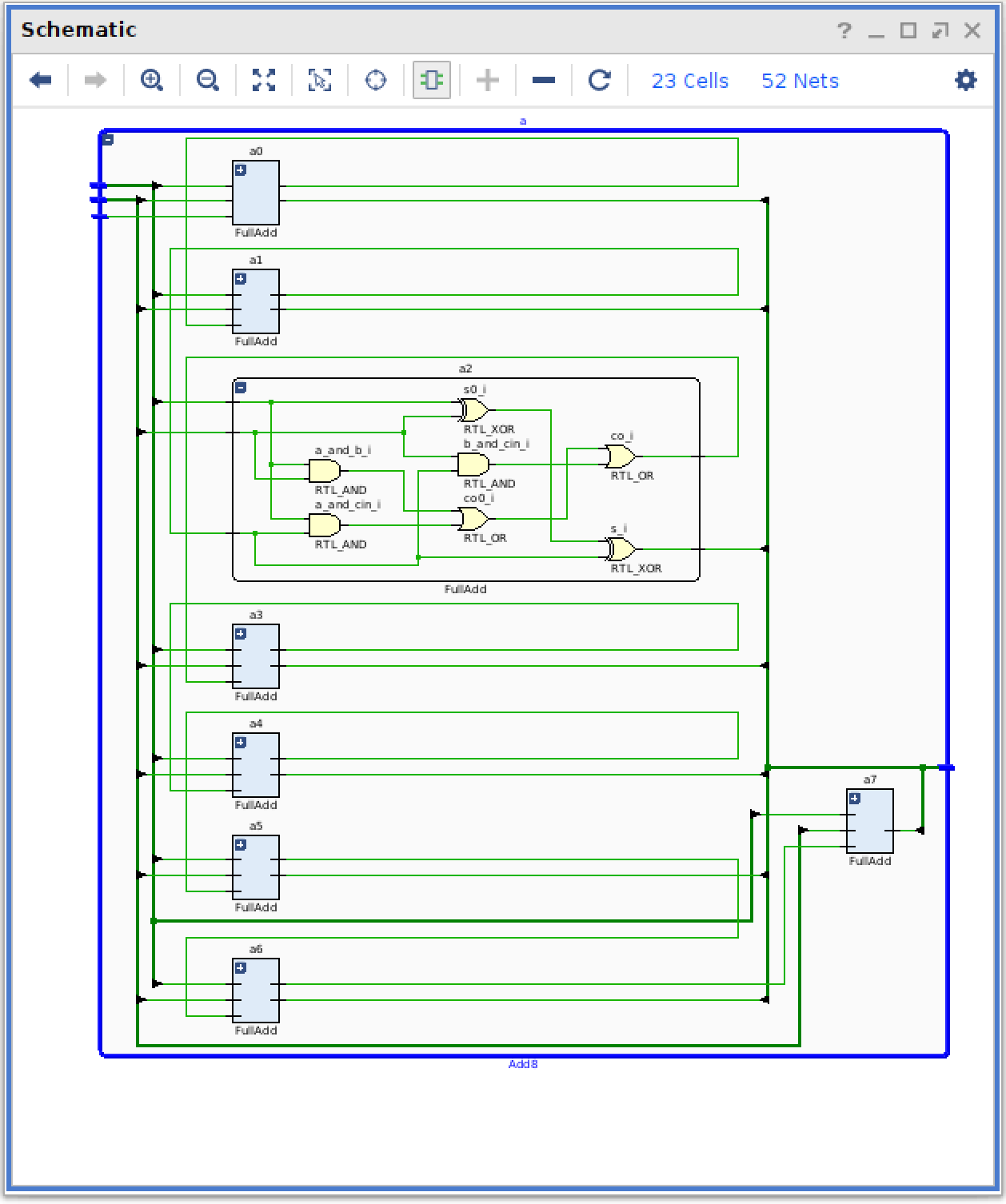
As you expand lower levels in the hierarchy the schematic will grow in size. You can use the ‘Zoom in’ and ‘Zoom out’ icons to manage your view in the schematic.