Table of Contents
This page gives some guidance in creating a Pong game on the VGA display.
Note that the video shows a wide-screen monitor, so there are “black bars” on the left and right that aren’t part of the drawable space.
Drawing Graphics on the VGA Display
Use the Bitmap Memory module to store and display a bitmap image on the VGA display. This module stores a 320x240 bitmap image, which is then scaled up to a 640x480 image by drawing each pixel as a 2x2 block on the VGA display. Given this, you will want to design your Pong graphics to fit within the 320x240 bitmap resolution.
Step 1: BallDrawer State Machine
Design a state machine that can be used to draw a ball. The module interface is described below:
| Module Name = ball_drawer | |||
|---|---|---|---|
| Port Name | Direction | Width | Description |
| clk | Input | 1 | 100 MHz Input Clock |
| reset | Input | 1 | Reset |
| start | Input | 1 | High to start drawing a ball, must go back low before drawing another ball |
| draw | Output | 1 | High when the module is outputting a valid pixel location to draw |
| done | Output | 1 | High on cycle that last pixel location is output |
| x_in | Input | 9 | Leftmost x-Coordinate of ball to be drawn |
| y_in | Input | 8 | Topmost y-Coordinate of ball to be drawn |
| x_out | Output | 9 | x-Coordinate to be drawn |
| y_out | Output | 8 | y-Coordinate to be drawn |
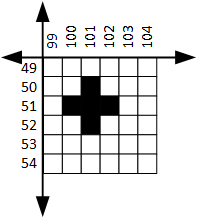
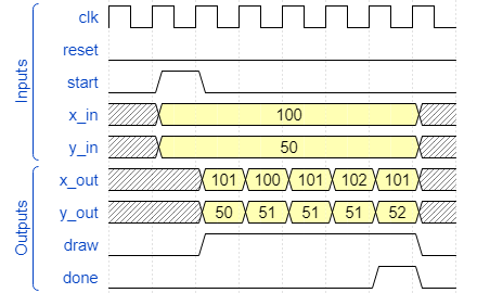
The following shows a diagram of a ball with 5 pixels, and a corresponding waveform for drawing this ball at (100,50).
Your state machine does not need to produce the exact same timing as the waveform above, but it does need to obey a few rules:
- The state machine should wait for the
startsignal before starting to draw a ball. - For each pixel that needs to be drawn, the state machine should output an (x,y) coordinate using the
x_outandy_outoutputs, and assert thedrawsignal to indicate that a valid pixel is being output. - The
donesignal should be asserted for exactly 1 cycle after the ball is done being drawn (or during the last pixel). - The state machine should wait for the
startsignal to go low before allowing another ball to be drawn.
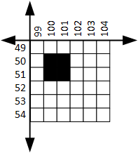
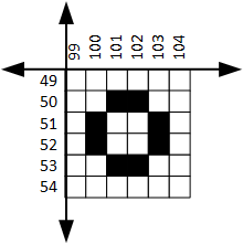
Here are some other ball shapes you can use, or you can design your own.
Consider creating a Tcl simulation to verify this module is working correctly before moving on to the next step.
Step 2: Line Drawer
Now that you have created a module to draw a ball, you will follow the same process to create a module that can draw vertical lines of arbitrary height.
Create the following module. Use a state machine to implement the described behavior.
| Module Name = VLineDrawer | ||
|---|---|---|
| Parameter | Default | Function |
| HEIGHT | 40 | Specifies the height of the line in pixels |
| Port Name | Direction | Width | Description |
|---|---|---|---|
| clk | Input | 1 | 100 MHz Input Clock |
| reset | Input | 1 | Reset |
| start | Input | 1 | High to start drawing a line |
| draw | Output | 1 | High when the module is outputting a valid pixel location to draw |
| done | Output | 1 | High on cycle that last pixel is drawn |
| x_in | Input | 9 | x-Coordinate of line to be drawn |
| y_in | Input | 8 | y-Coordinate of top of the line |
| x_out | Output | 9 | x-Coordinate to be drawn |
| y_out | Output | 8 | y-Coordinate to be drawn |
This module should work very similarly to your BallDrawer module, except now there is a HEIGHT parameter that dictates the height of the line. Since the height can be changed, you can’t use one state per pixel being drawn. Instead, your state machine will need to interact with a counter to keep track of how many pixels you need to draw.
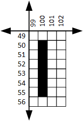
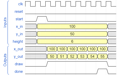
The following shows a diagram of a line 6 pixels tall, and a waveform for drawing this line at (100, 50).
You may want to simulate this module before moving on.
Step 3: Pong State Machine
| Module Name = pong | |||
|---|---|---|---|
| Port Name | Direction | Width | Description |
| clk | Input | 1 | 100 MHz Clock |
| reset | Input | 1 | Active-high reset |
| paddle_up_l | Input | 1 | Move left paddle up |
| paddle_down_l | Input | 1 | Move left paddle down |
| paddle_up_r | Input | 1 | Move right paddle up |
| paddle_down_r | Input | 1 | Move right paddle down |
| vga_x | Output | 9 | X-coordinate to draw |
| vga_y | Output | 8 | Y-coordinate to draw |
| vga_color | Output | 3 | RGB color to draw |
| vga_wr_en | Output | 1 | Write enable for VGA bitmap memory |
The Pong module should instance the ball drawer and line drawer modules you created in the previous steps.
Create a FSM that implements the following game loop:
- Draw one paddle
- Draw the other paddle
- Draw the ball
- Wait for some time (somewhere between 0.1s and 0.001s is a good choice, depending on how fast you want the game to play)
- Erase one paddle (by drawing it in black)
- Erase the other paddle (by drawing it in black)
- Erase the ball (by drawing it in black)
- Update the location of the ball and paddles based on the game logic (ball bouncing, paddle movement based on button inputs, etc.)
- Go back to the first step
You will need to create some registers and counters for the following:
- A timer to keep track of how long to wait in the wait state
- The location of the ball and paddles
- The direction of the ball (moving up or down, moving left or right). The ball will only move at a 45 degree angle, so you don’t need to keep track of any velocity components.
- The score (leave this for last)
The following diagram shows how the FSM can interact with the various other components in the module.
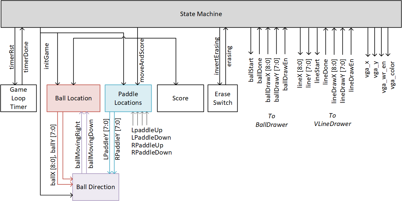
Note: The above shows an erase switch that controls whether the drawing states should draw in background to erase. This is done to reuse the same drawing states for both drawing and erasing, which reduces the amount of states needed. However, it is also possible to implement this FSM without an erase switch, and instead have separate states for drawing and erasing. This is up to you.
Note: You only need one instance of the ball drawer and line drawer. Even though you are drawing multiple paddles, drawing and erasing the ball multiple times, only one instance of each module will be used. You can just use the same instance for each paddle and for the ball, and change the input coordinates and colors as necessary.
How to approach creating this system:
- Create the FSM with just the states needed to start the game and draw the objects (the first few states)
- Move on to the top-level module and test this on the board, and then come back to finish the rest of the FSM and components.
- Add the states delaying, erasing, and redrawing. Check that these work correctly.
- Add the logic to update the ball and paddle locations based on the game rules.
- Add logic to keep score.
Step 4: The Top-Level Module
Create a top-level module that:
- Instances the pong module
- Instances the VGA timing generator module
- Instances the bitmap memory module. Connect the
pixel_xandpixel_youtputs of the VGA timing generator to the read inputs of the bitmap memory, and connect the color outputs of the bitmap memory to the VGA output. Connect the signals from the pong module to the write inputs of the bitmap memory. - Display the score on the seven segment display.