Table of Contents
In order to run simulations and synthesis in Vivado, you must call several Vivado executables with the appropriate parameters. Rather than doing this manually each time, it is often more convenient to create a Makefile that automates this process for you.
Instead of having you create your own Makefile from scratch for each lab (this requires a lot of repetitive work), we have created a common Makefile called common.mk that you can use in all of your Vivado labs.
Makefile Organization
In each of your labs you will be creating multiple hardware designs (called modules) that you will need to simulate and synthesize.
Each of these modules will have its own Makefile that includes the common.mk file.
You will also have a Makefile in the lab directory that will handle cleaning temporary files (removing the work/ directories) and any other lab-wide tasks (you don’t have these until later labs).
So, for the lab_tools lab, you should have:
lab_tools/Makefile- Lab-wide Makefilelab_tools/binary_adder/Makefile- Makefile for simulating and synthesizing thebinary_addermodulelab_tools/logic_function/Makefile- Makefile for simulating and synthesizing thelogic_functionmodule. This will be given to you empty and you will fill it in.
The rest of this tutorial describes the different commands provided by the common.mk file, and which variables you need to set in your Makefile to use them.
The common.mk File
In the Makefiles you create for each lab, you will include this common.mk file and set a few variables that are specific to your design. The common.mk file will then use these variables to run the appropriate Vivado commands for simulation and synthesis. The include statement is similar to the #include statement in C/C++, and copies the contents of the specified file into your Makefile.
Take a look at the Makefile provided in the lab_tools/binary_adder/ directory to see how this is done.
You will see that it includes the common.mk file and sets several variables that are used by the common.mk file to run simulation and synthesis.
Here are a description of the different variable that the common.mk file uses.
Required Variables
REPO_PATH: Path to the root of the repository. Start each module Makefile by defining this variable and including the common.mk file. Example:REPO_PATH=../.. include $(REPO_PATH)/resources/common.mkMODULE_NAME: Top-level module name of the design. Example:MODULE_NAME = arithmetic_topSV_FILES: List of SystemVerilog source files for the design. Example:SV_FILES = arithmetic_top.sv \ ../add_8/add_8.sv \ ../full_add/full_add.sv
Optional Variables
SIM_PARAMS: Parameters to pass to the top-level module during simulation. Example:SIM_PARAMS = REFRESH_RATE=500000 WAIT_TIME_US=50SYNTH_PARAMS: Parameters to pass to the top-level module during synthesis. Same format asSIM_PARAMS.
Simulation (Tcl Script)
As you learned in the Vivado Command Line Simulation Tutorial, simulation is done by first analyzing the design files with xvlog, elaborating the design with xelab, and then simulating the design with xsim. Take a look these lines in the common.mk file to see how this set is run.
- Command:
make simormake_sim_nogui - Required files:
sim.tcl(Tcl script to run the simulation) - Output files:
sim.log(log file of the simulation process)
Simulation (Testbench)
You can also run a simulation using a SystemVerilog testbench file instead of a Tcl script.
You are provided with testbench files (e.g., tb.sv) for certain modules throughout the course.
Take a look these lines in the common.mk file to see how this set is run.
- Command:
make sim_tb - Required files:
tb.sv - Output files:
sim_tb.log(log file of the simulation process)
You can also use make sim_tb_gui to run the simulation with the Vivado GUI open.
This will not run the testbench, but will allow you to manually advance the simulation time to simulate a portion of the testbench.
Pre-Synthesis Schematic
This command will run Vivado, analyze your SystemVerilog files, and generate a schematic of your design using generic logic gates (i.e., before synthesis to FPGA resources). The command does this by running Vivado and sourcing this Tcl script.
- Command:
make pre_synth_schematic - Output files: None (you must take a screenshot manually).
When you are asked to save a screenshot of the pre-synthesis schematic, you should save it as <module>/pre-synth-schematic.png.
Synthesis
Logic synthesis is the process of converting your design from a SystemVerilog description to a set of FPGA resources, called a netlist. This netlist lists the FPGA resources and how they are connected together. The command does this by running Vivado and sourcing this Tcl script.
- Command:
make synth - Output files:
synth.log(log file of the synthesis process)synth.dcp(design checkpoint file)synth.v(human-readable netlist file)
Post-Synthesis Schematic
Once you have synthesized your design, you can view a schematic of the netlist using this process.
First, run this command to open the synthesized checkpoint in Vivado:
make open_synth_checkpoint
This will bring up a window with the device Design and several panes that contain information about your design. The window should look something like below (this is not the actual schematic, continue the steps below to open the actual schematic):

The Device window on the right provides an overview of the FPGA resources that the design will be mapped to. In the top-left is the Netlist window that summarizes the details of the design (internal nets and cells). The bottom left window provides a summary of the netlist.
To open the post-synthesis schematic, do the following:
- Select the
binary_adderin the Netlist Pane. - Right Click and select Schematic
When you are asked to save a screenshot of the post-synthesis schematic, you should save it as <module>/post-synth-schematic.png.
Implementation
Implementation is the process of mapping the netlist to the actual resources on the FPGA. It makes decisions about which specific LUTs and IOs to use, and how to route the connections between them. It then generates a bitstream file that it used to program the FPGA. The command does this by running Vivado and sourcing this Tcl script.
- Command:
make implement - Output files:
implement.log(log file of the implementation process)utilization.rpt(utilization report file, describing how many FPGA resources were used)timing.rpt(timing report file, describing the speed performance of the design, used in later labs)design.dcp(design checkpoint file after implementation)design.bit(bitstream file to program the FPGA)
Download Bitstream to FPGA
The final step is to download the generated bitstream file to the FPGA on the Basys3 board.
- Command:
make download
The Vivado tools can be used to query the layout of your logic implementation on the FPGA.
This tutorial will describe how you can view the internals of the FPGA mapped with your design.
This tutorial is written with your lab03 logic_functions.sv design.
Before proceeding with this tutorial, you need to have fully implemented your design and have a file named `logic_functions.dcp.
Vivado Device Viewer
You can open your implemented design in Vivado like so:
make open_implement_checkpoint
This will bring up a window with the Device viewer, and several panes that contain information about your design. The window should look something like:
This image shows the internals of the FPGA resources and your design resources mapped onto the FPGA. Since your design is relatively small, your design resources are not easiliy noticable.
To view the location of design resources, expand the Leaf Cells line within the Netlist Pane.
This will list all of the design resources mapped to the FPGA.
The type of resources is indicated in paratheses after the resource name (e.g., IBUF or LUT3).
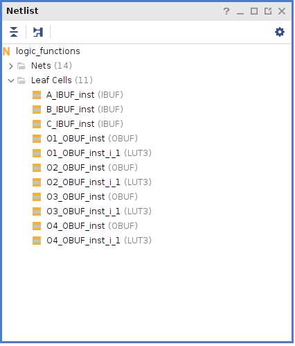
Select one of the LUT* resources in your list.
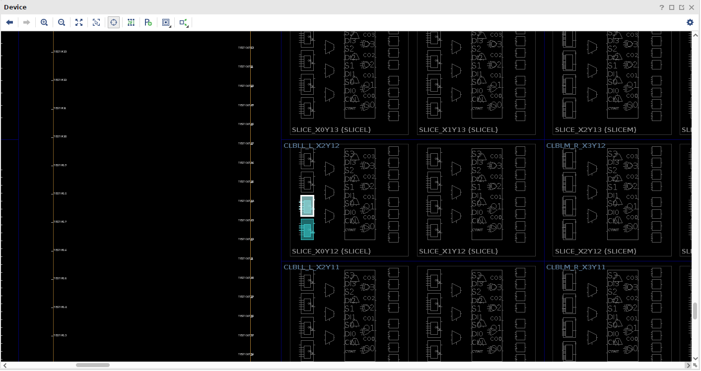
After you select a resource, click ‘Auto-fit Selection’ button: ![]() .
The design viewer will then zoom into the area of the device that contains the resource with the resource highlighted.
An example looks like this:
.
The design viewer will then zoom into the area of the device that contains the resource with the resource highlighted.
An example looks like this:
By default, this view only shows the cell resources and not the net resources.
Enable the viewing of the net resources by clicking on the Routing Resources button: ![]() .
.
You can zoom in and out of the design with the following buttons:
- Full Zoom:

- Zoom Selection:

- Zoom In:

- Zoom Out:

You can also view specific nets within the design.
Select a net in the Netlist Pane under the Nets line.
After selecting the net, Click the Zoom Selection button![]() .
.
When you are asked to save a screenshot of a specific part of the implemented design using the device viewer, you should save it as <module>/fpga.png.