Table of Contents
In the center of this board is an Integrated Circuit (IC) device called a Field Programmable Gate Array or FPGA (this is the square device labeled ARTIX-7). This FPGA device is the heart of the board and contains the programmable digital logic that you will use in most of your lab exercises. An FPGA device is a programmable digital circuit that can be configured to perform different functions based on the user’s digital design. Other major components of the Basys 3 board that you will use this semester include:
- 4-digit seven-segment display
- 16 switches
- 16 LEDs
- 5 push buttons
- a USB/UART interface
- a VGA display interface More details about this board can be found by referring to the Basys3 Reference Manual.
During the course of the semester you will be creating digital designs that will be configured onto the FPGA of the Basys3 board.
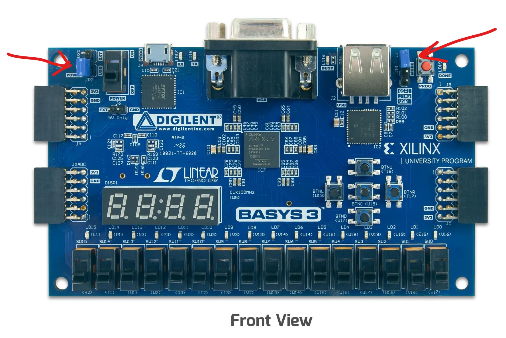
Jumpers
To use your board, the jumpers need to be set properly. Check to make sure the blue jumpers are set as shown below. Do not turn on the board until you verify that the jumpers are set correctly.
Switches and LEDs
A primary user input to the FPGA circuit on the Basys3 board are the toggle switches. The board contains 16 switches (named SW15-SW0) in a row on the bottom of the board with SW0 being the right-most switch and SW15 being the left-most switch. The switches are labelled on the silkscreen of the circuit board (the silkscreen is the white text on the board that labels the components on the board). Each switch can be placed in the Up (ON or binary 1) or Down (OFF or binary 0) position. You will be using the switches in your future laboratory assignments and for a number of the activities in this exercise in this lab.
The Basys3 board also contains 16 light-emitting diodes (LEDs) located directly above each switch. These LEDs are labelled LD15-LD0 with LD0 being the right-most LED and LD15 being the left-most LED. The FPGA circuit configured on the FPGA can set the value of each of these LEDs. The LEDs can provide output functionality for user circuits.
Push Buttons and Seven Segment Display
Another form of input to the FPGA circuit on the Basys3 board are the five push buttons. The five buttons are organized in a cross pattern on the right side of the board. The buttons are named based on their position on the cross pattern. “BTNC” is the center button, “BTNL” is the left button, “BTNR” is the right button, “BTNU” is the up button, and “BTND” is the down button. The buttons will provide a logic ‘1’ input to the FPGA while the button is pressed and a logic ‘0’ when the button is released.
The Basys3 board also has a four-digit “seven-segment display”. Each digit of the seven-segment display can display a hexadecimal number from 0 to F. With four digits, a four-digit seven-segment display can display a 16-bit hexadecimal number. You will design a seven segment display controller in a future lab.
Basys 3 Video
The video below is an overview of the Basys 3 board. Watch it.
Then, look through the board reference below to see what it contains.