Table of Contents
Overview
This lab works with two different features of the Y board:
- Accelerometer
- GPIO pins (General Purpose Input Output)
Equipment and Materials
• (1) Y-board • (1) Breadboard • (4+) Jumper wires • (1+) LEDs from Kit • (1+) Switches from Kit • (1) USB data cable
Procedure
Getting the starter code
- Open vs code.
- Click the “Source Control” button on the left toolbar.
- Click “Clone Repository”. Note: if you do not see the option to Clone Repository then you will need to open a new window of VisualStudios Code (VSCode)
- Enter the url: https://github.com/byu-ecen-192/y-board-accelerometer-gpio.git and hit Enter.
- A window will open and ask you to select the destination folder. Choose where to put it.
- Open the PlatformIO Project.
- Build and Upload the code in the main.c file to the Y-Board.
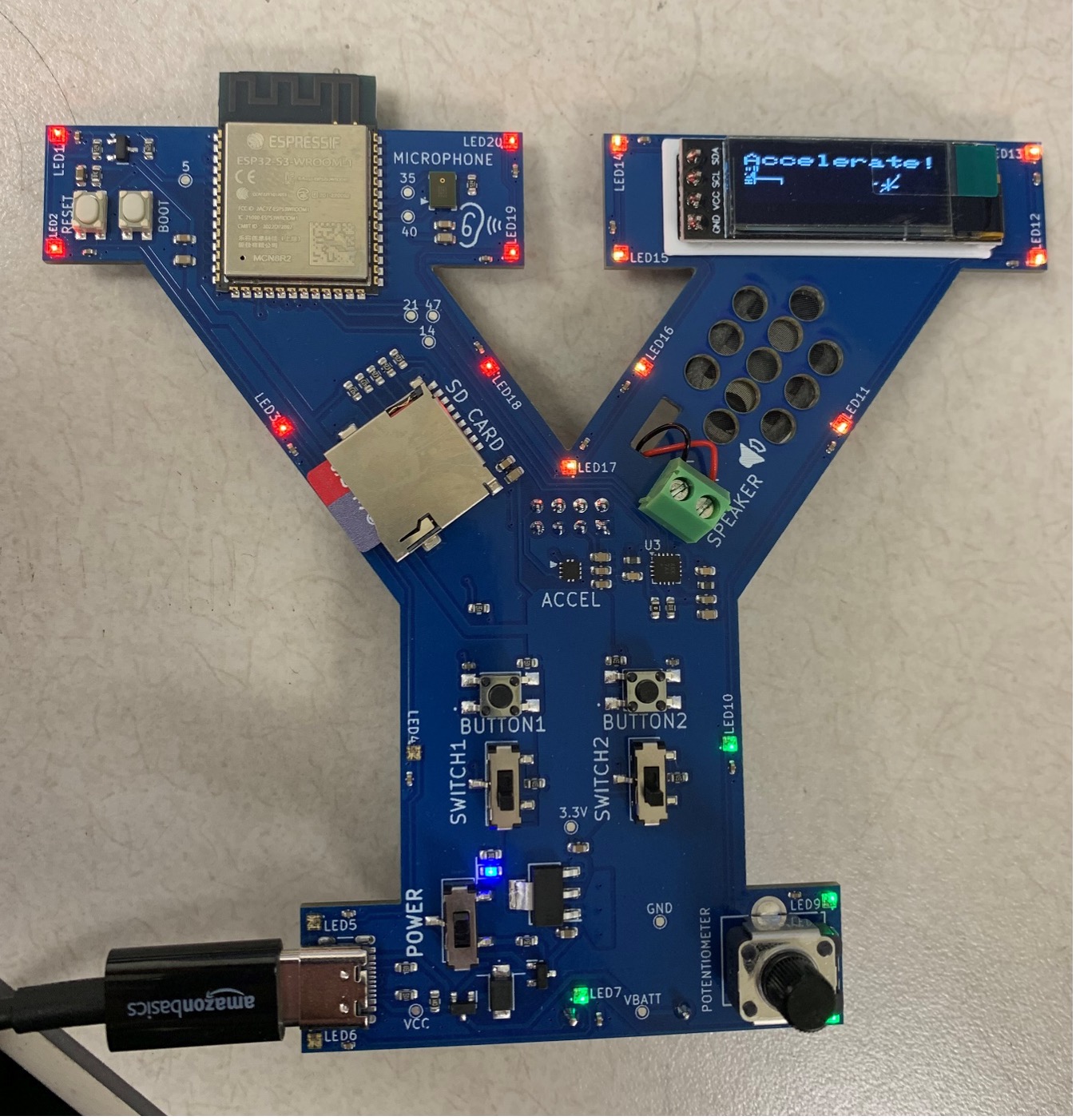
Part 1: The Accelerometer
defaultProgram() Function
This function displays accelerometer data on the OLED screen. It’s defined in accelerometer.cpp.
- Uncomment the call to defaultProgram(), upload the code, and observe how the accelerometer data is displayed.
- Experiment with moving the board around and get familiar with how the data reacts.
light_LEDs() Function
This function maps accelerometer data to the onboard LEDs. The LEDs change color based on how the board is tilted or rotated in 3D space.
- Uncomment the call to light_LEDs(), upload the code, and move the Y-board around.
- Don’t forget to flip it upside down to see the full range of motion.
Part 2: GPIO
The GPIO pins allow the Y-board to interface with external peripherals, like LEDs, sensors, or motors. The GPIO header is on the back of the Y-board.
Blink_LED() – Microcontroller to Breadboard
We’ll start by using code that can turn a breadboard LED on and off. Here’s how:
- Comment out the accelerometer functions (defaultProgram() and light_LEDs()).
- Uncomment the pinMode() call on line 25 and the blink_LED() call on line 47.
- Read the comments around the blink_LED() function at the bottom of main.cpp—you’ll have the chance to modify this later, so start thinking of creative extensions.
- Upload the code.
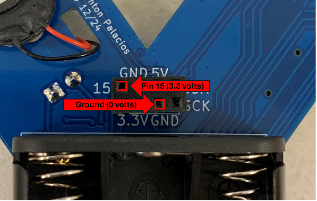
- Connect jumper wires to pin 15 (3.3 volts) and ground GND (zero volts)
- Set up your breadboard:
- Place an LED in the breadboard.
- Connect the GPIO jumpers to the breadboard.
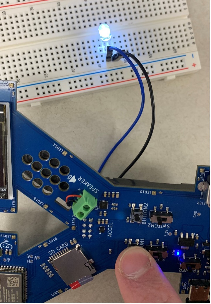
- Press Button 1 on the Y-board. The LED should light up.
- Pull out your breadboard, put an LED in the breadboard, and connect the GPIO jumpers to the breadboard. When you press button 1, the LED should light up.
- Troubleshooting Tips:
- If the LED doesn’t light up, try flipping the LED (polarity matters—the long lead should go to 3.3V).
- Press the reset button on the Y-board, or power cycle the board.
onboard_led() – Breadboard to Microcontroller
This function allows external signals (like a switch) to control the onboard LED.
- Comment out the previous functions (pinMode() and blink_LED()).
- Uncomment the pinMode() call on line 26 and the onboard_led() call on line 50.
- Read the comments around onboard_led() at the bottom of main.cpp to understand how it works—you’ll modify this later.
- Upload the code.
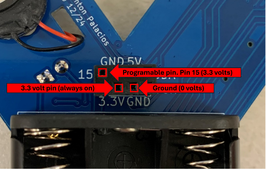
- Add a third wire to the back of the Y-board:
- 3.3V pin (always on) (see picture below)
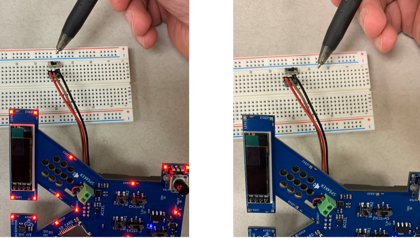
- Set up a switch on the breadboard:
- Connect the Pin 15 jumper to the center lead of the switch.
- Connect GND to one side and 3.3V to the other.
- Flip the switch back and forth to control the onboard LED.
Part 3: Creativity Time – Build on These Functions
Now that you’ve seen how to:
- Control a breadboard device from the microcontroller (output)
- Use a breadboard switch to control the microcontroller (input) …you’re ready to get creative. Your kit has way more than just LEDs and switches—there’s temperature sensors, photoresistors, fans, and more.
Example Ideas
-
Fan Control with a Button: Rebuild the fan circuit from Lab 5. Instead of using a photoresistor to drive the transistor, modify the circuit so the Y-board controls the fan. For example, press Button 1 to turn the fan on.
-
Temperature Display: Modify onboard_led() so it reads from an LM61 temperature sensor and displays the temperature on the OLED screen. (Reference Figure 15 from Lab 3 for the correct schematic.)
You could even use this prompt with ChatGPT for code help:
Adapt onboard_led() in this file: COPY MAIN.CPP HERE so that PERIPHERAL_PIN reads the analog voltage from an LM61 temperature sensor, then displays the temperature on the Y-board’s OLED screen. Use these screen commands: display.setTextSize(3); display.setCursor(0, 0); display.print(“Word”);
-
Want even more ideas? Ask ChatGPT, or just start experimenting. The goal is to get comfortable blending code with hardware—the sky’s the limit.
Background
An accelerometer (“acceler-“ and “-meter”) is a circuit chip that measures the acceleration that chip experiences (from the inside). The gist of how one works is that there is a very small, delicate spring inside of the chip that also acts as part of a circuit. As that spring compresses or relaxes, the properties of the circuit change in a way that can be revealed by measuring the voltage in the circuit.

“GPIO” stands for general purpose input & output. From an engineer’s perspective, GPIO pins are pins that the engineer can program to do pretty much whatever he/she wants. They’re pins that don’t have a predetermined purpose, allowing the engineer flexibility to incorporate and interface with new components to meet his/her project-specific needs.
The GPIO pins on your Y-board are found on the back. While there are six pins, only three of them are actually GPIO. This is because three of them are reserved as 5V, 3.3V, and GND. Two of the GPIO pins can additionally support a communication named I2C. We rely on those pins’ support of that protocol in order to send data from the accelerometer to the off-board OLED display.