Table of Contents
Overview
This lab covers motors, sensors, and actuators. You will be building 3 different circuits using a fan motor.
Procedure
Basic Setup
We will want to tape our motor to the table. This is to prevent the fan from moving around randomly when it is on.
Circuit 1 Switch Controlled Fan
For this Circuit we need our battery, motor, and a switch.
Follow the circuit diagram below:

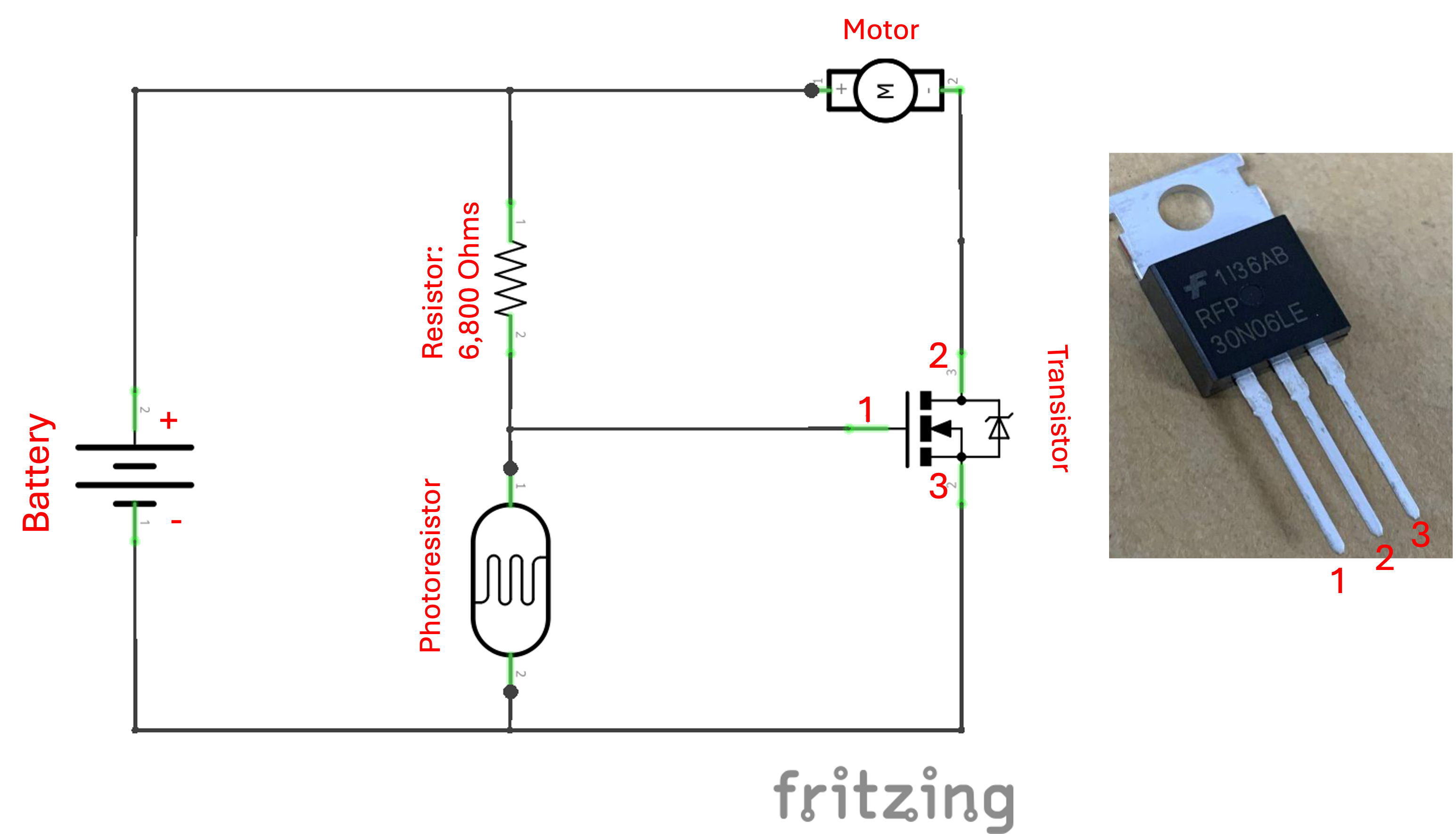
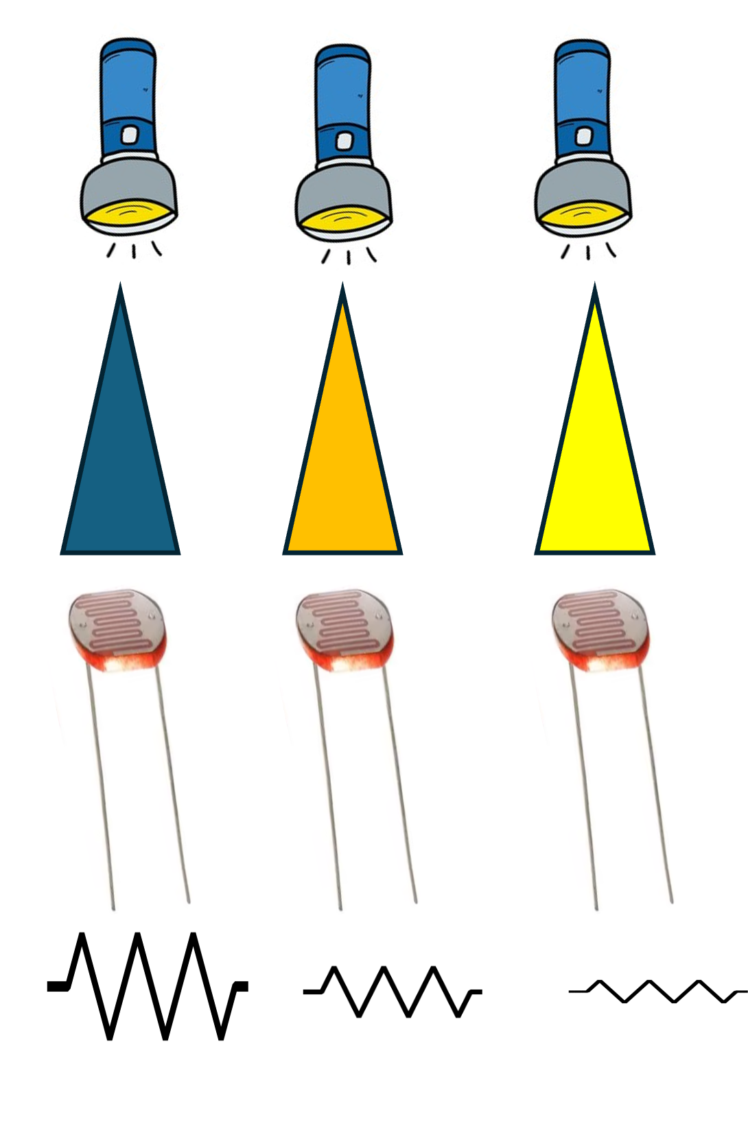
Circuit 2 Light Sensor Controlled Fan
For this Circuit we need our battery, motor, transistor, photoresistor, and resistor about 6.8kOhms.
Follow the circuit diagram below:
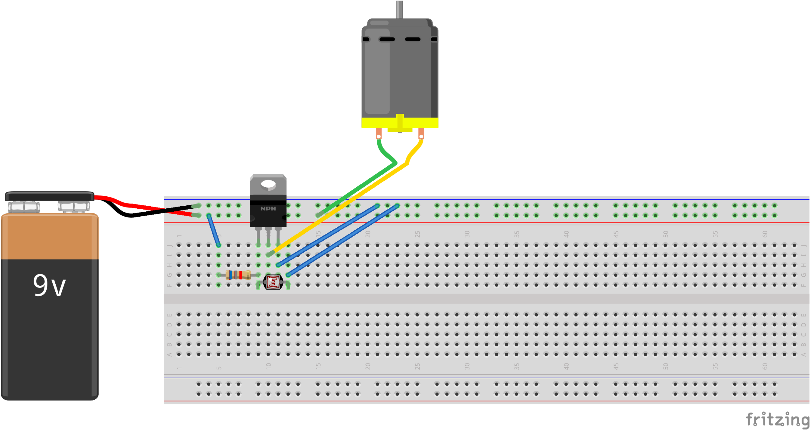
Here’s one way you could configure this circuit. WARNING! If connected incorrectly, the transistor can get REALLY hot and burn your finger, so please be carful!
Circuit 3 Potentiometer Controlled Fan
For this Circuit we need our battery, motor, switch, and potentiometer.
Follow the circuit diagram below:
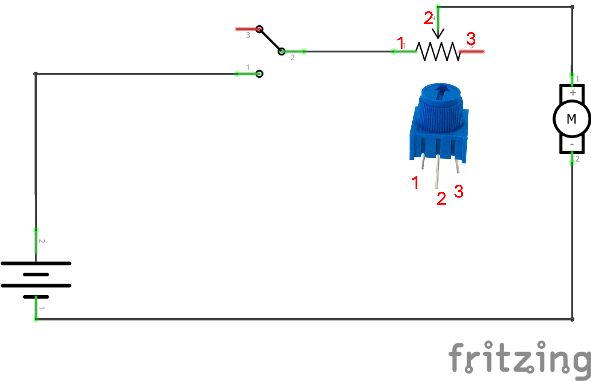
Note: The Red lines on the switch and potentiometer do not need to be connected to anything. They will be floating nodes.