Table of Contents
Overview
In this lab we will be using some tools you are likely already familiar with to measure DC voltage, DC current, and resistance. Now that you know how to create and operate circuits using breadboards, it’s time to learn how to use multimeters.
Background/Preparation
Introduction to Ohm’s Law
$$ I = \frac{V}{R} ~~ or ~~ V = IR $$
We often compare this law to water in pipes.
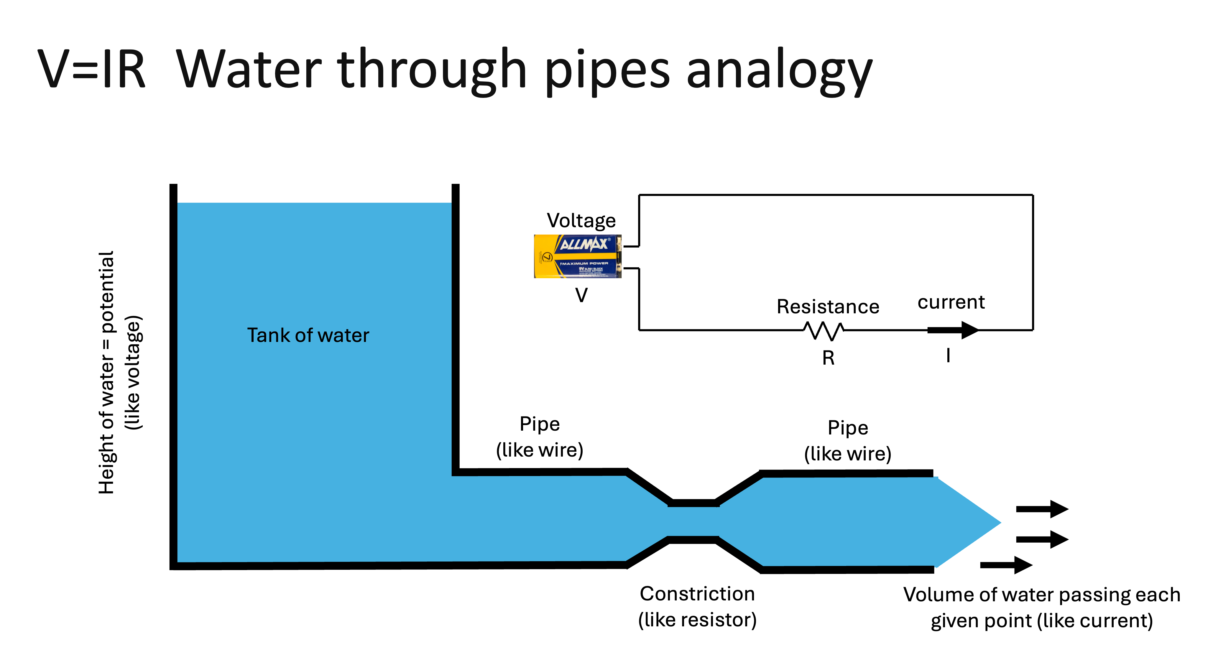
- Voltage is the pressure of the water in the pipe - higher pressure pushes more water down the pipe.
- The resistance is the size of the pipe - a larger pipe allows for easier water flow through the pipe.
- The current of the pipe is the actual amount of water flowing through any given cross section of the pipe.
| Variable | Unit | Symbol |
|---|---|---|
| Current | Ampere | A |
| Voltage | Volts | V |
| Resistance | Ohms | Ω |
Introduction to Multimeters
Most multimeters can measure DC voltage, AC voltage, DC current, resistance, can perform diode tests, and can measure battery resistance.
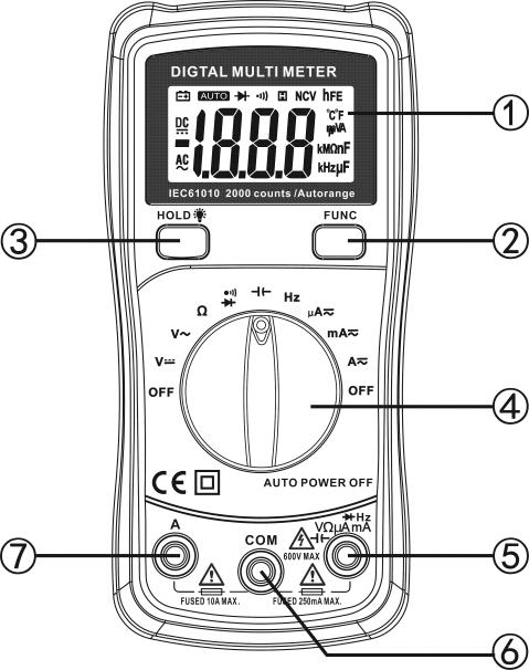
1. LCD display
2. “FUNC” Push button
3. “BACK LIGHT” push button and ‘HOLD” push button
4. Rotary Switch (Knob)
5. “V/Ω/HZ/uA/mA”Input terminal
6. “COM” input terminal
7. “10A” input terminal
Image credit: Neoteck User Manual
Warning: Before you use a multimeter, you need to know what values you expect to encounter and select the appropriate scale. Failure to do so can overload the multimeter and may even cause a short circuit, which can be dangerous to you, and permanently damaging to both the circuit and the multimeter.
Equipment and Materials
-
Multimeter
-
Led (1) (Any color)
-
Potentiometer (1) (23 kΩ)
-
Resistors: 250 Ω, 360 Ω, 750 Ω, 10 kΩ, 5 kΩ, 68 kΩ,
-
Jumper Wires (10)
-
Breadboards (1)
-
9V battery (1) (6A)
-
Alligator clips (2)
-
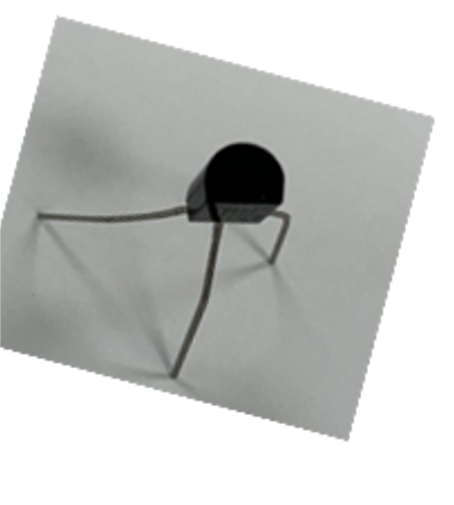
Temperature Sensor (1)
-
Battery Screw Terminal (1)
Procedure
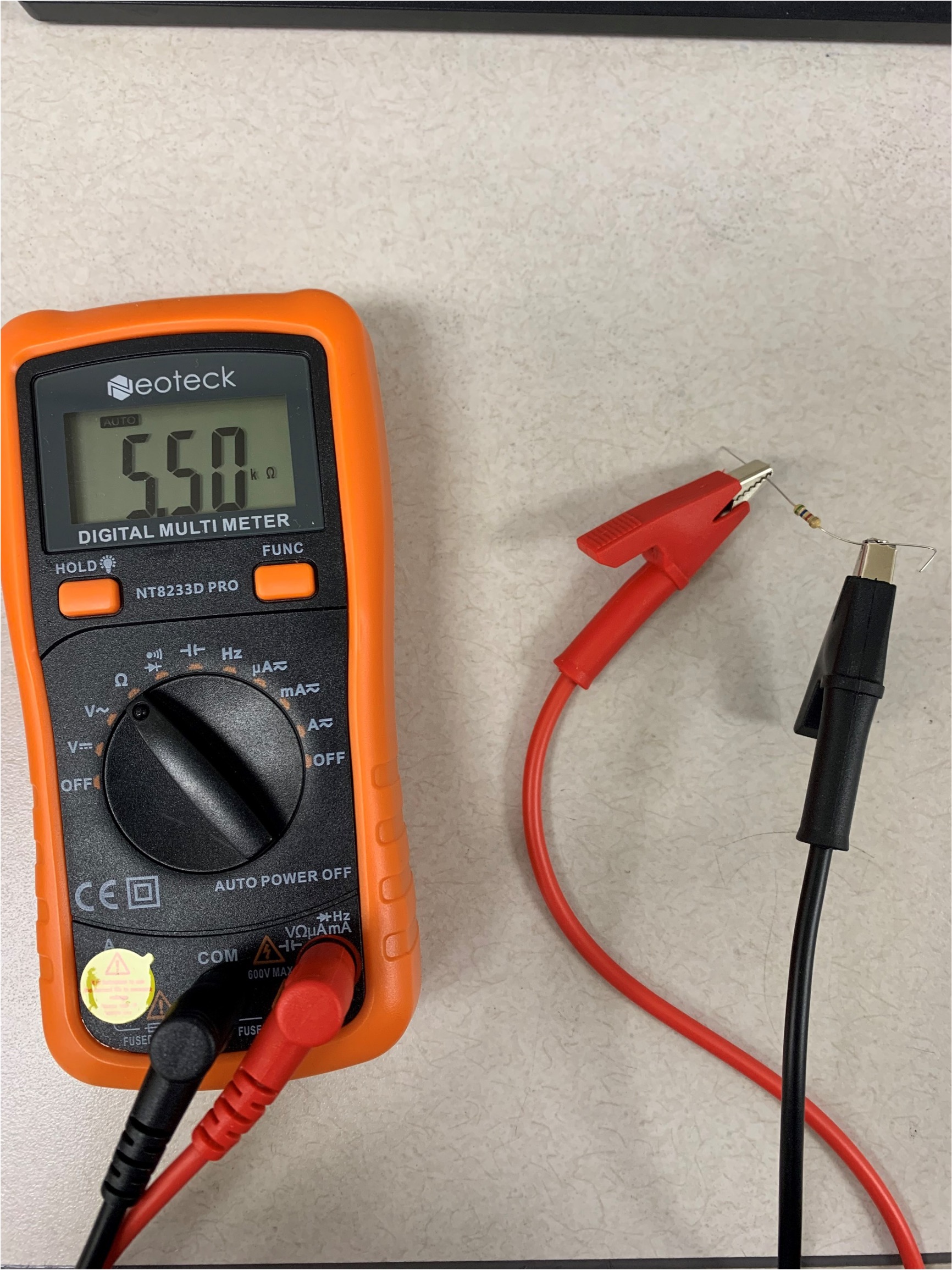
Resistance
Remember: Make sure you have the multimeter to measure resistance (Ω symbol)

-
Grab some resistors from the red bag
-
Read their color codes to figure out their resistance
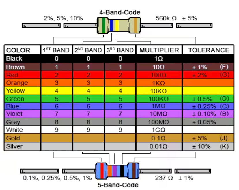
Image Credit: Digi-Key Electronics
-
Check with the online calculator ( Resistance Calculator )
-
Confirm by measuring with the multimeter
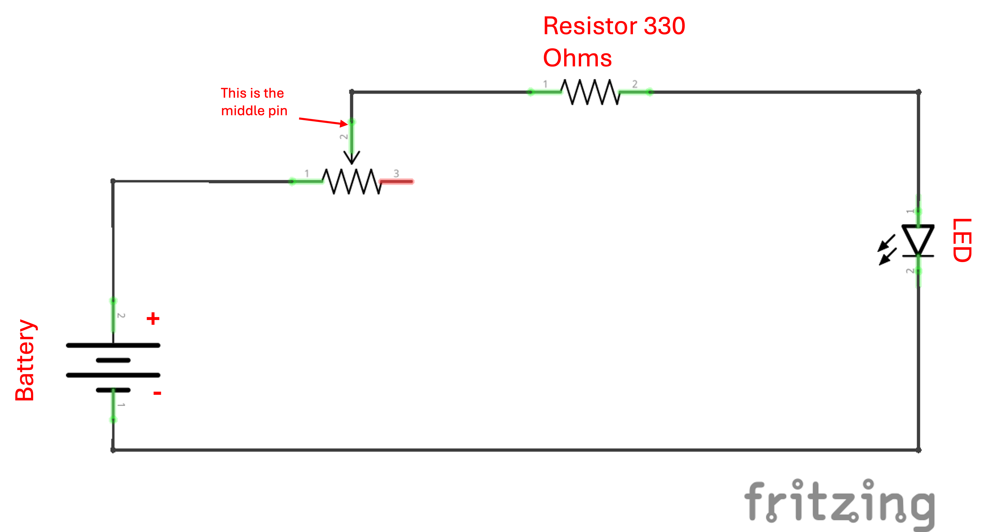
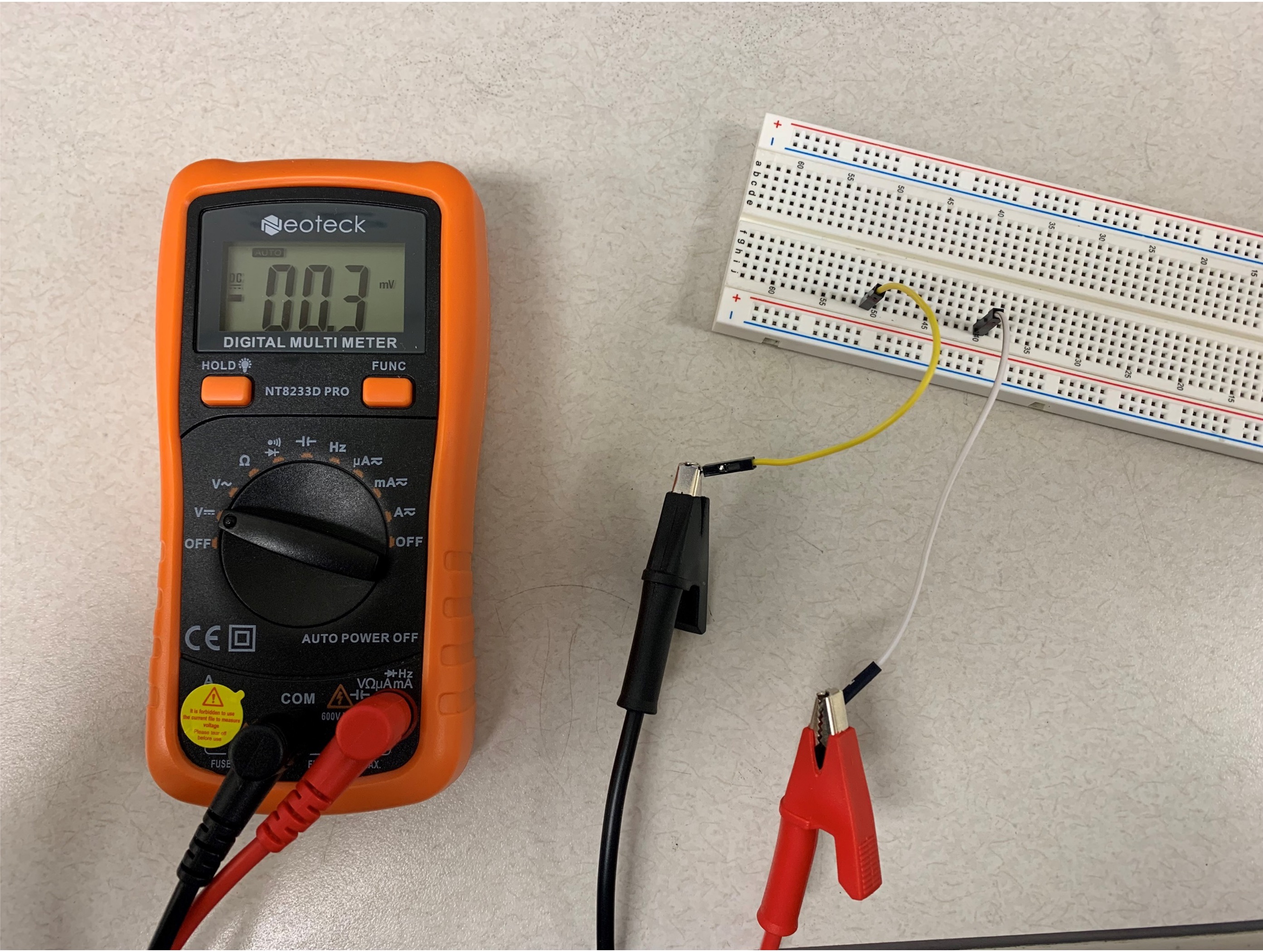
Voltage
Note: Make sure you have set the multimeter in the right setting to measure DC voltage (V symbol).

-
Build the circuit
-
Connect the multimeter
-
Measure how the voltage potential across the LED
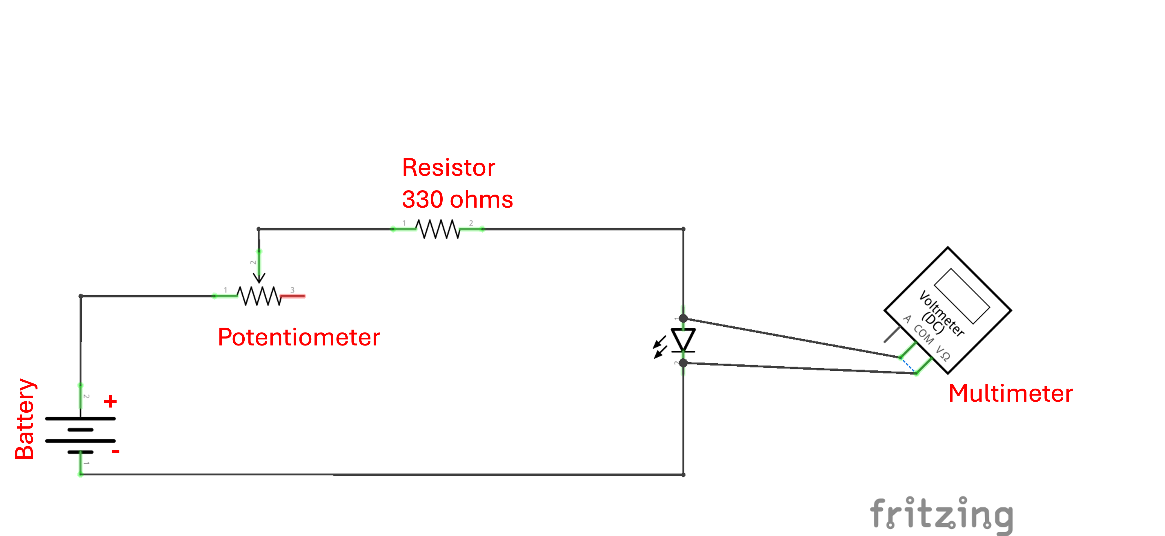
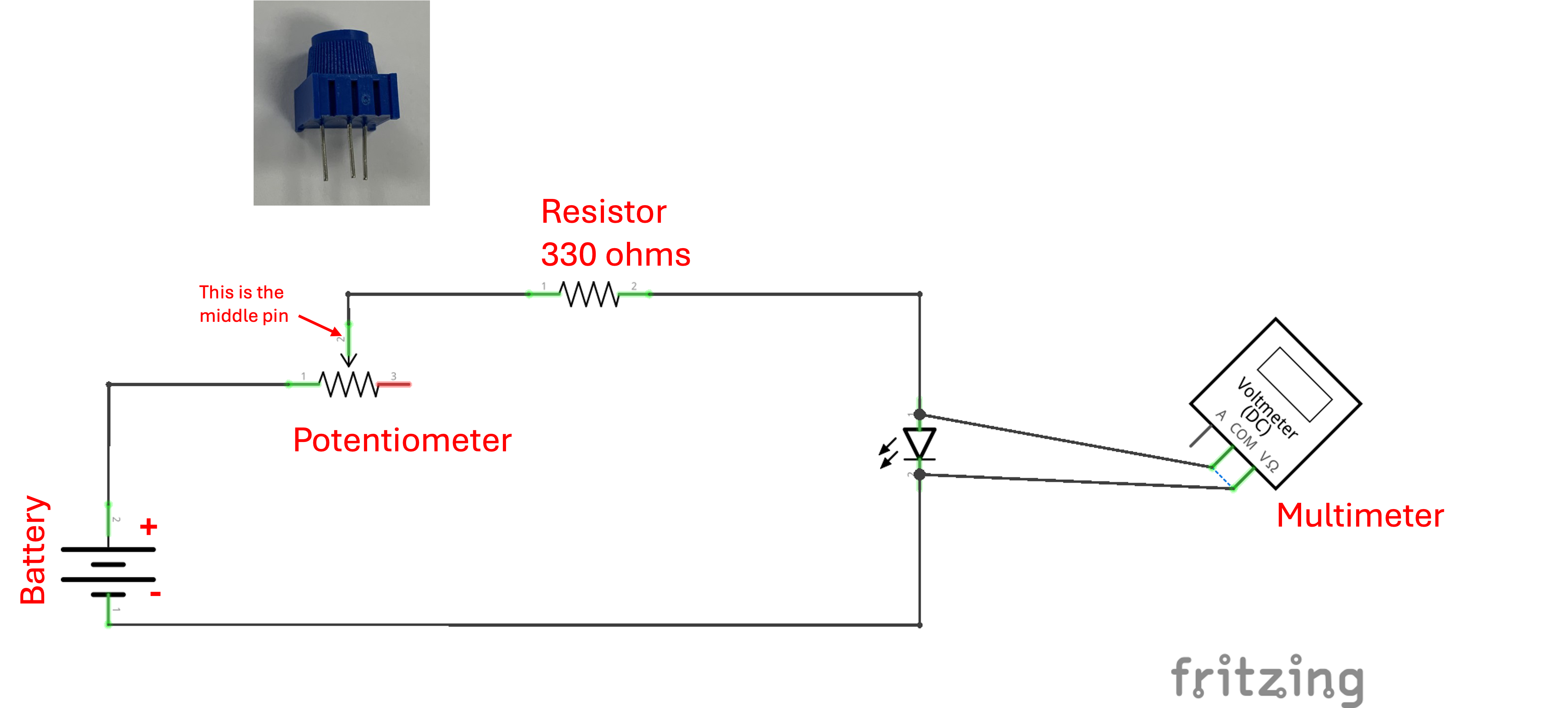
This circuit uses a potentiometer that changes resistance based on how much it is turned.
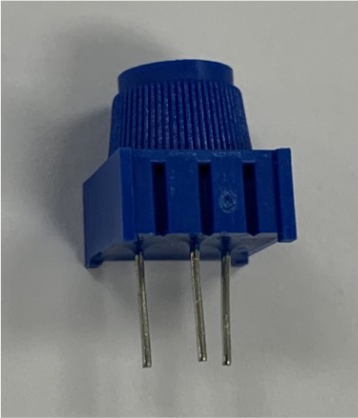
Image Credit:Electronix Express. (potentiometer) and Physical Computing and Craft Technologies, University of Washington. (potentiometer pinout)
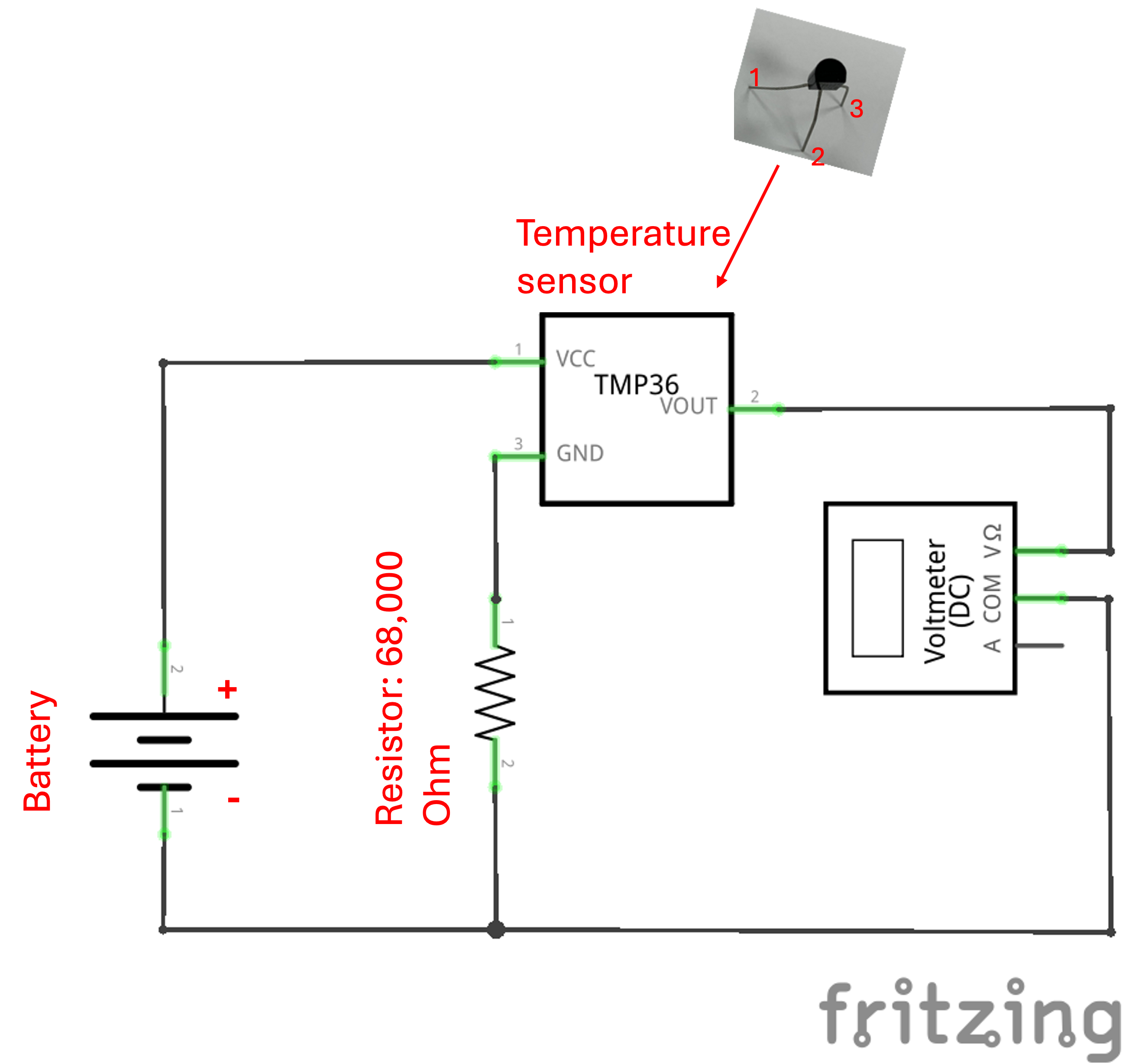
Measure Varying Voltage
We will be using a temperature sensor for this lab; a temperature sensor contains a resistor that changes its resistance with temperature.
- Breadboard the circuit
-
Connect the multimeter
-
Measure voltage
-
Pinching the temperature sensor with your fingers will increase its temperature, causing the voltage to change.
-
Observe how the voltage changes as you pinch the temperature sensor with your fingers
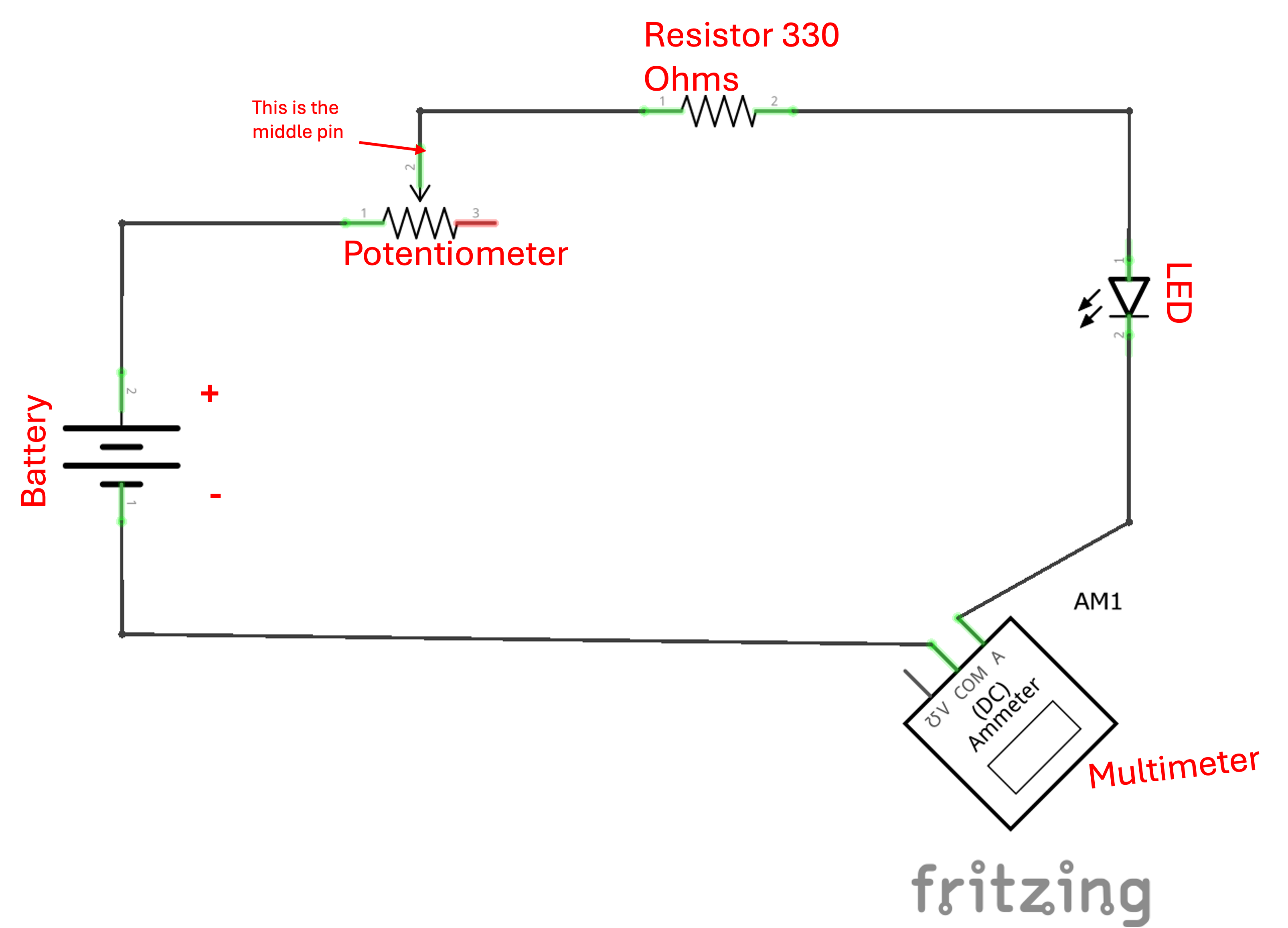
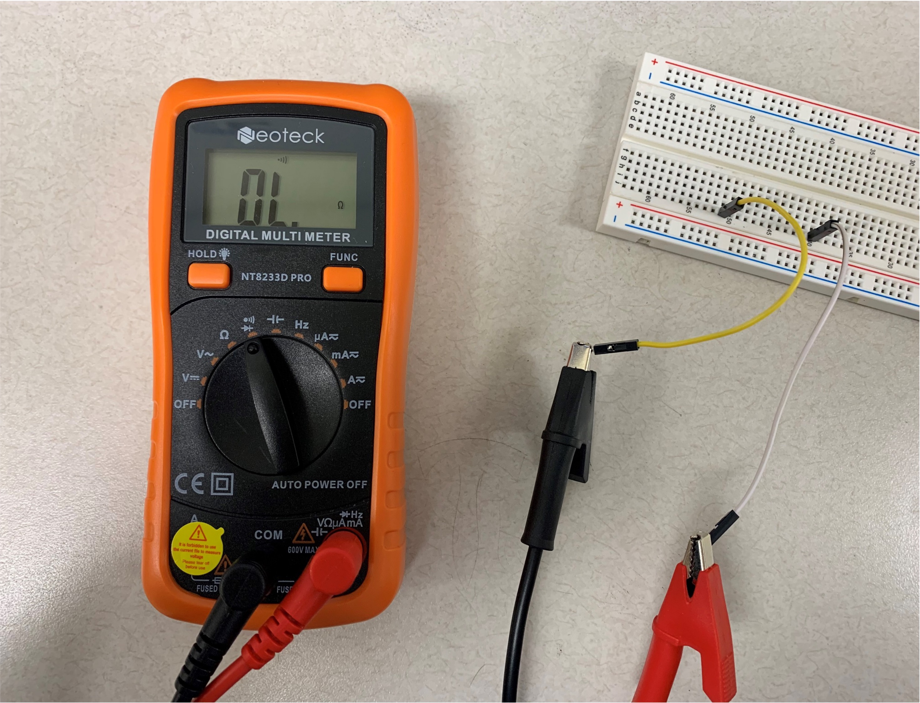
Current
Note: Make sure you have set the multimeter in the right setting to measusre DC current (A symbol).

-
Build the circuit
-
Connect the multimeter
- Measure the current
- Google what current should typically pass through an LED
- Adjust the potentiometer and observe how the current changes