Table of Contents
Overview
A breadboard, in circuitry, is a tool used primarily for prototyping or simple circuit development. They are especially useful because of their ability to be changed easily and their ability to work with a multitude of components. In addition to breadboards, we will be using LEDs and wires to create three or four circuits to better understand why breadboards are useful and how they function.
In todays lab you will:
- Setup your breadboard
- Build a simple LED circuit
- Build a Traffic Light with 3 LEDs
- Build a buzzer circuit
- Explore and Build a different circuit of your choosing
Background/Preparation
Intital Setup
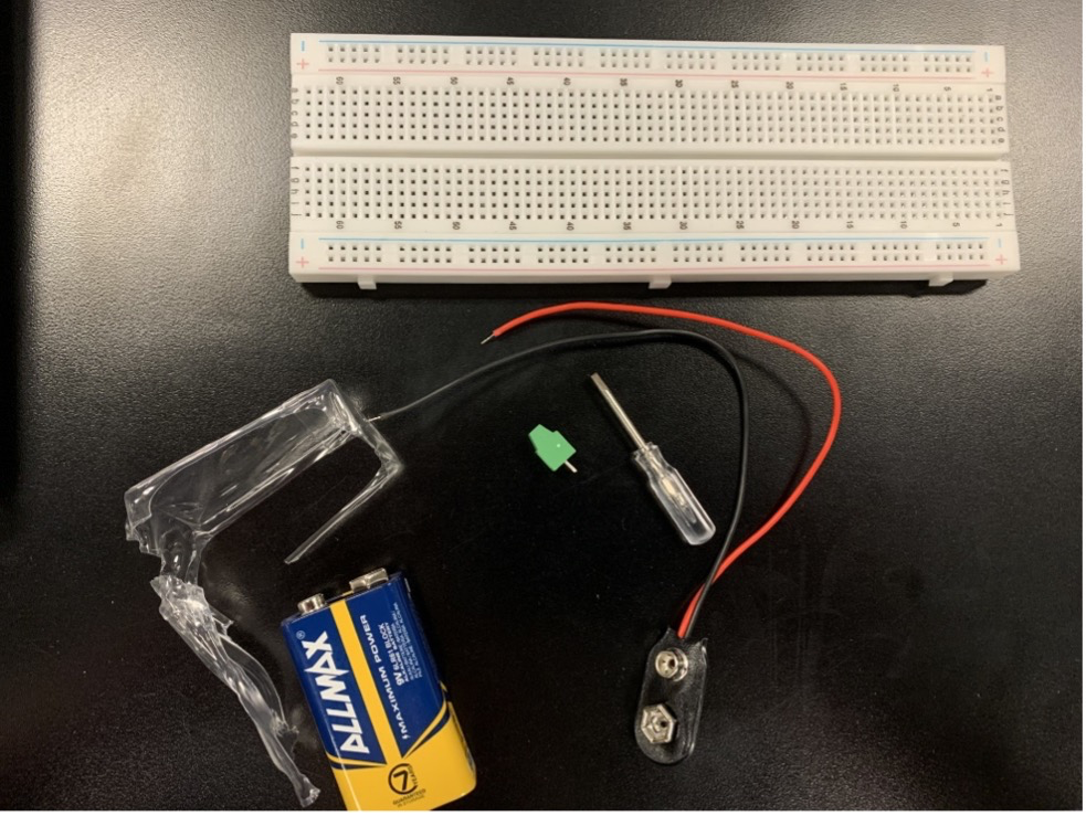
You have your breadboard, battery, battery connector and terminal pins.
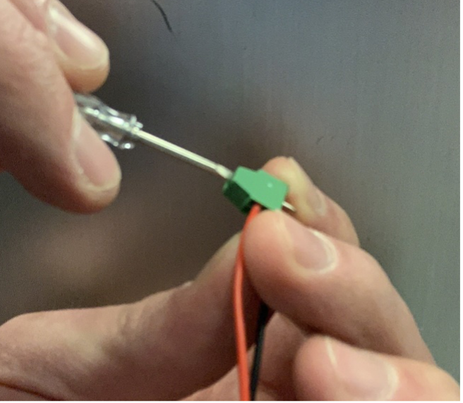
Screw the red and black wires from the battery connector into the terminal.
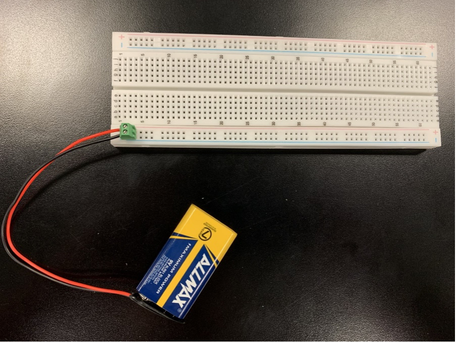
Put the terminal into the breadboard to match the red with the red rail and black with the blue rail.
Equipment and Materials
- breadboard
- at least four LED lights
- at least four resistors
- button
- wires to connect components
- DIP Switch
- power source (battery, connector and screw terminals)
- button
- buzzer
Procedure
Simple LED Circuit
Turn on an LED. Use the components in the bag with the BLUE dot
Follow the diagram below to set up the components. Use the schematic to also compare the two and pay attention to how are they the same circuit.
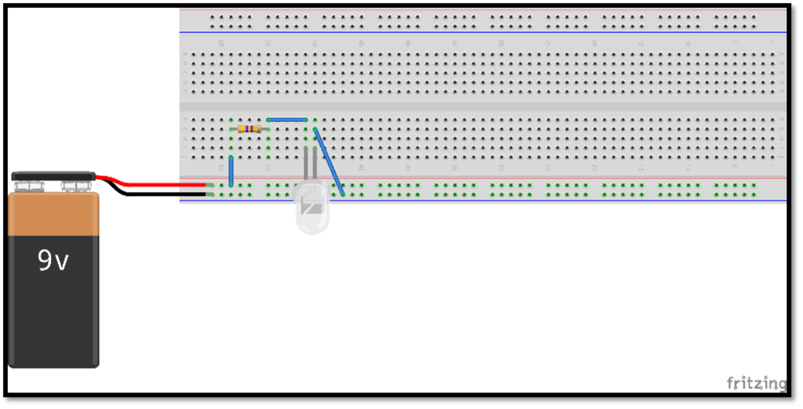
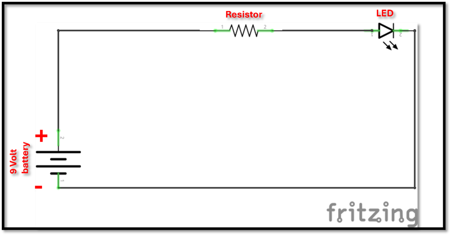
Before you plug the LED in, notice - Light-Emitting Diodes, are unidirectional, meaning that they only allow current to flow in one direction. Most manufacturers denote which side is which by making the positive node (or cathode) longer than the negative node (or anode). Ensure that your LED is plugged in the right direction!
Traffic Light Circuit
Make a traffic light. Use the components in the bag with BLUE dot
We will utilize a dipswitch (a name for that type of switch) placed over the DIP Support gap. Again, see the image below for help. Make sure the switches are fully in the ON or OFF positions.
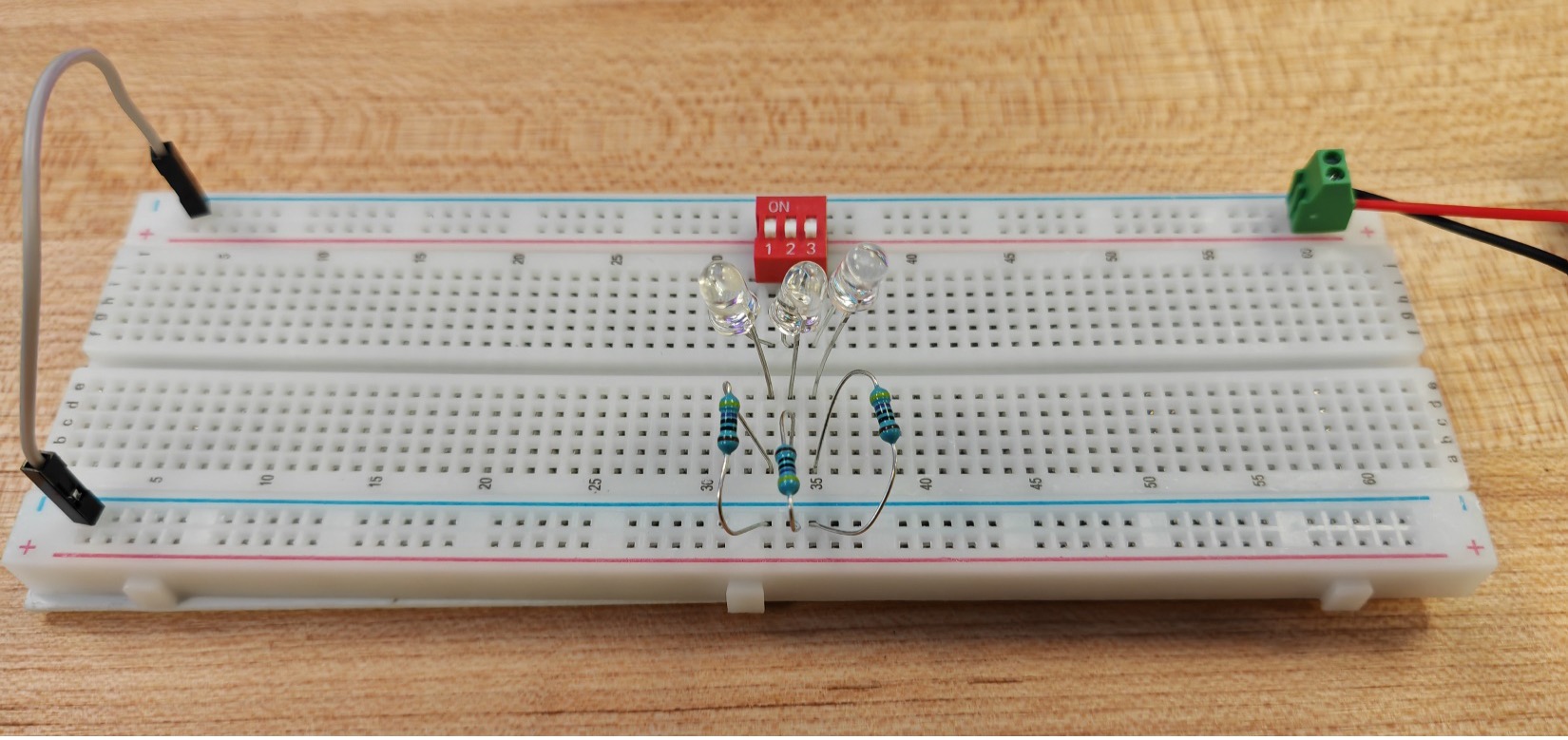
Make sure the ground is connected on both sides of the breadboard. If you have a split rail make sure the ground rails are also connected.
Buzzer Circuit
Make a buzzer circuit. Use the schematic to take the 4 components and connect the on the breadboard in order to make it turn on an LED and a buzzer everytime you press a button.
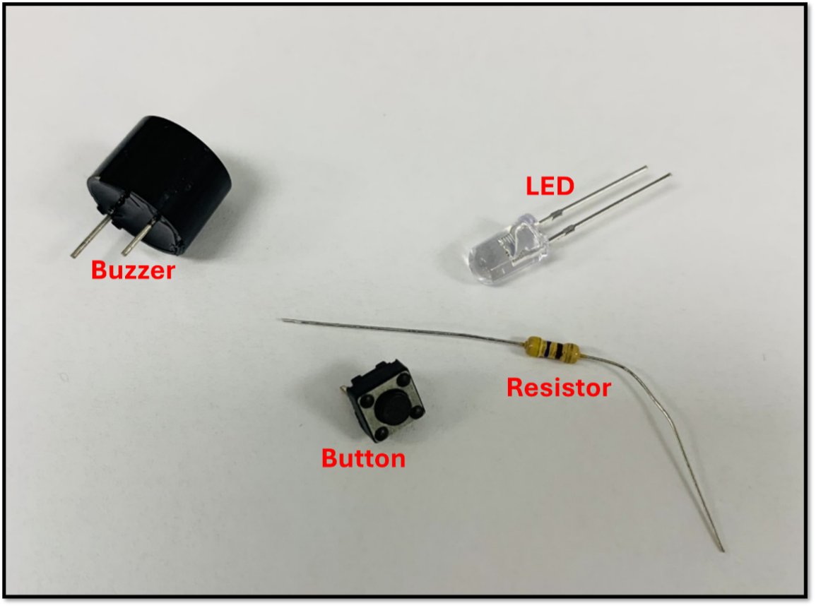
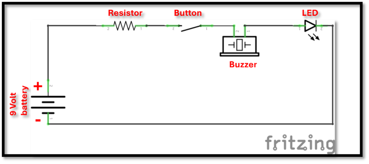
Notice: while it is a diode like the LEDs, buzzers are more fragile than the LEDS are. If you set up the buzzer’s polarity in the wrong direction, the buzzer could break. To avoid this, ensure that it is going in the right direction by pointing the cathode (the side indicated as “positive” on the top of the component) to the positive side of the circuit. Hopefully though, even if the buzzer breaks, electricity will still flow, so the rest of the circuit should still work.
Further Exploration
Using these bins of random components, build your own circuit. For the components you chose, how do they work? What interesting thing can you do with these components?
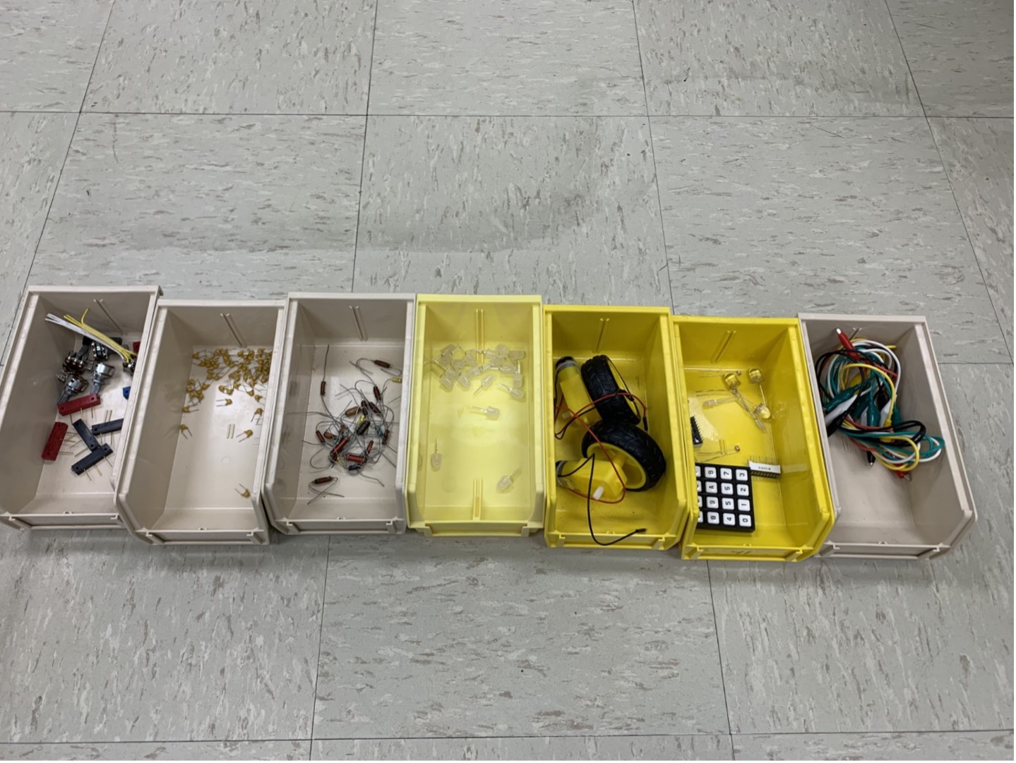
Some ideas:
- LEDs in a line, in a matrix.
- Charge capacitors and discharge them across LEDs
- Figure out how to connect a potentiometer (variable resistor) and how to use it to dim an LED.
After trying something try drawing the schematic of what you made.
If you want to do this more on your own, you can also visit the ECEn shop to buy any number of other parts. Almost any part you can think of comes in a version that will fit on a breadboard.
Additional Information and Resources
Help Video
Breadboards
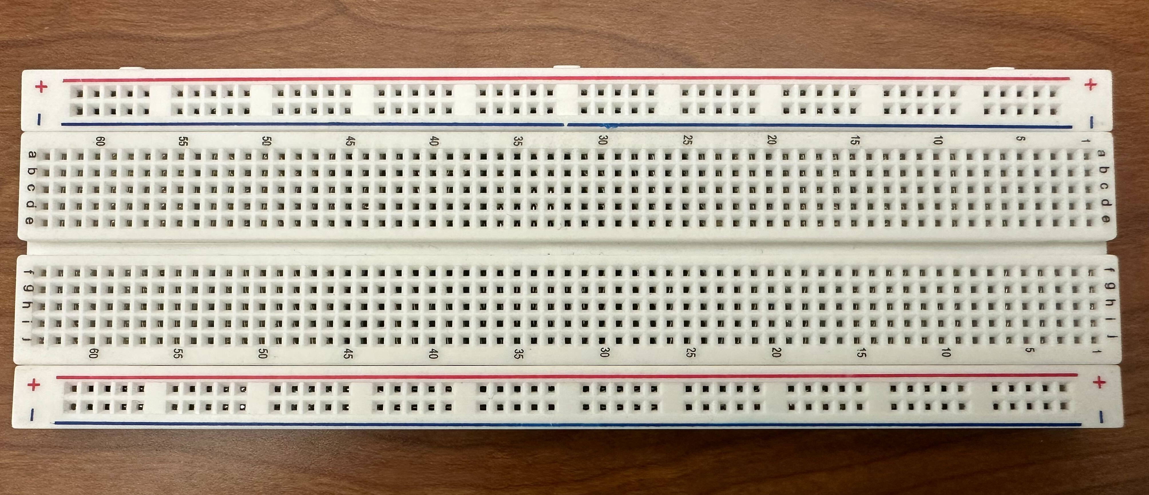
Breadboards function in different rows and columns, commonly referred to as busses. All the pinholes on the breadboard that are connected to one another make up a single bus. If two wires or components are plugged into the same bus, they are connected to each other at those points. The busses that run along the long sides, for example, are referred to as the power rails. These power busses are marked by red and blue lines, which serve to help keep track of positive and negative polarities when powered elements are used in the circuit.
Note: While busses have helpful notation, there are no rules specifically forcing you to plug things in correctly. Always make sure you double check the polarity and pins you choose when plugging in components to avoid damaging parts.
In contrast to the power rails along the long side, terminal strips are busses that run perpendicular to the power rails along the short sides of the breadboard. These are marked by numbers on the ends of some of the terminal strips. There are two sets of terminal strip rows which are separated by the DIP Support (Dual In-line Package), a measured gap that allows for more circuit components to fit nicely across multiple terminal strips. Traditionally, components that don’t supply power are plugged into the terminal strips, which are, in turn, connected to the power rails by wires or resistors that then receive the power from somewhere off the breadboard. Another way to picture how this works is to look at the inside of the breadboard itself:
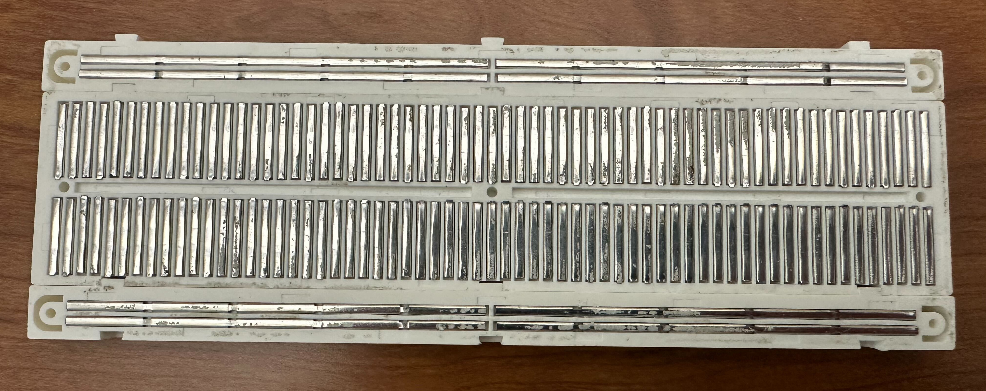
Breadboard busses are notable as they support connections without requiring you to manually attach every component with solder or another permanent method. What we will be doing today is utilizing a breadboard to create various circuits.